Programmable DC Power Supply (with Solar Array Simulation) 62000H Series
Operating & Programming Manual
4. Use the “ ”, “ ” keys to move the cursor to the M/S TERMINATOR
selection item.
5. Use the numeric keys ( -
) or the “Rotary” ( ) knob to ENABLE or
DISABLE the TERMINATOR as shown in Figure 3-38.
6. Press “ ” to confirm.
7. Press “ ” to return to the MAIN PAGE.
3.3.3.3.2 Setting MASTER
If MASTER OR SLAVE is set to MASTER, M/S TERMINATOR, PARALLEL OR SERIES and
NUM. OF SLAVE selections also need to be set. See the description of PARALLEL OR
SERIES in section 3.3.3.3.3 and NUM. OF SLAVE in section 3.3.3.3.4.
MASTER has two main functions:
(1) It issues commands to all SLAVE units, such as voltage setting, current setting, and
protection setting, etc., which means all settings in SLAVE units are set from the
MASTER. The original settings in the SLAVE units are temporary ignored.
(2) It accepts all measurement values and protection signals from the SLAVE units. The
MASTER calculates all measurement values and displays them in the MAIN PAGE.
When a protection error occurs in one SLAVE unit, the MASTER will notify the other
SLAVE units to turn ON protection and display the error on the MASTER’s main page.
When multiple DC Power Supplies are connected in series or parallel,
only one DC Power Supply can be the MASTER and the rest must be set
Configure a unit as MASTER as described below:
1. In the Config Setup page, press “ ” then to select PARALLEL/SERIES.
2. Use the numeric key (
) or the “Rotary” ( ) knob to set MASTER as shown in
Figure 3-39.
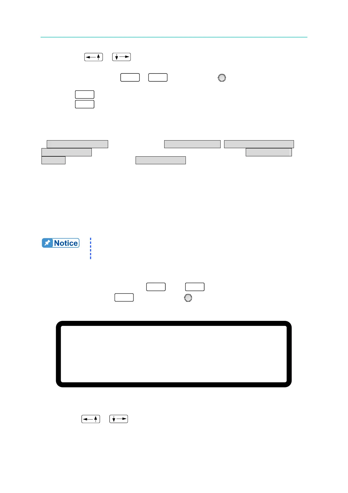
[ S E R I E S
/ P A R A L L E L ]
M A S T E R O R S L A V E =
M A S T E R _
M / S T E R M I N A T O R
= D I S A B L E
P A R A L L E L O R S E R I E S
= P A R A L L E L
N U M . O F S L A V E
= 1
M A S T E R & S L A V E C O N T R O L = N O
Figure 3-39
3. Use the “
”, “ ” keys to move the cursor to the M/S TERMINATOR selection
item.