Manual Operation
4. Use the numeric keys ( -
) or the “Rotary” ( ) knob to ENABLE or
DISABLE the TERMINATOR as shown in Figure 3-39.
5. Press “ ” to confirm.
Description of M/S TERMINATOR
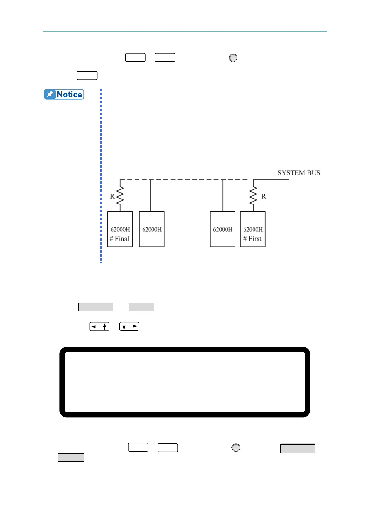
When the 62000H Series Models with Solar Array Simulation are
operating in MASTER OR SLAVE mode, be aware of the M/S
TERMINATOR setting. Assuming the connection is as shown in Figure
3-40, the M/S TERMINATOR of the first and last devices must be
ENABLED with a 120Ω internal resistance. When using A620028 and
A620027 SLAVE models, the TERMINATOR is installed externally as
shown in Figure 3-36.
3.3.3.3.3 Setting PARALLEL or SERIES
Set the Power Supply to Series or Parallel mode as shown in Figure 3-41. There are two
selections: PARALLEL and SERIES.
1. Use the “
”, “ ” keys to move the cursor to the column to be set.
[ S E R I E S / P A R A L L E L ]
M A S T E R O R S L A V E = M A S T E R
M / S T E R M I N A T O R
= D I S A B L E
P A R A L L E L O R S E R I E S
= P A R A L L E L _
N U M . O F S L A V E
= 1
M A S T E R
& S L A V E C O N T R O L = N O
Figure 3-41
2. Use the numeric keys (
- ) or the “Rotary” ( ) knob to set PARALLEL or
SERIES.