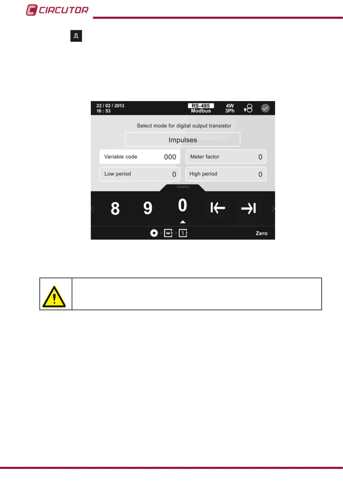
5.6.16.2.- Impulse mode of transistor digital output
When selecting the impulse mode, Figure 133, the conguration parameters are:
The variable code that controls the transistor.
The energy meter factor.
The high and low impulse period.
Figure 133: Conguration screen of transistor digital outputs (impulse mode).
The parameter selected is indicated in white.
It is possible that the unit may measure energy exceeding its conguration. Make
sure the energy pulses correspond to the maximum energy level admitted by the
installation.
To program the transistor digital output, after conguring the variable code and the pulse time
(with the low period and high period parameters), the following formula provides a method for
calculating the number of output pulses according to the generated energy so that the pulses
do not accumulate.
3600 * PE / PT > MP → PE = MP * TP / 3600
Where:
MP : Maximum power of the installation in W.
PE: Pulse energy in Wh ( Energy meter factor )
TP : low period + high period, in seconds.
For example: If the installation can consume 100kW, a suitable conguration could be pulses
of 10W ( Energy meter factor) with a high and low period of 50 ms.
The following options appear in the lower area:
158
CVM-B100 - CVM-B150
Instruction Manual