1-75
Cisco ONS 15454 Troubleshooting Guide, R8.5
November 2009
Chapter 1 General Troubleshooting
1.5.3 Perform a Hairpin Test on a Source-Node Ethernet Port
1.5.3 Perform a Hairpin Test on a Source-Node Ethernet Port
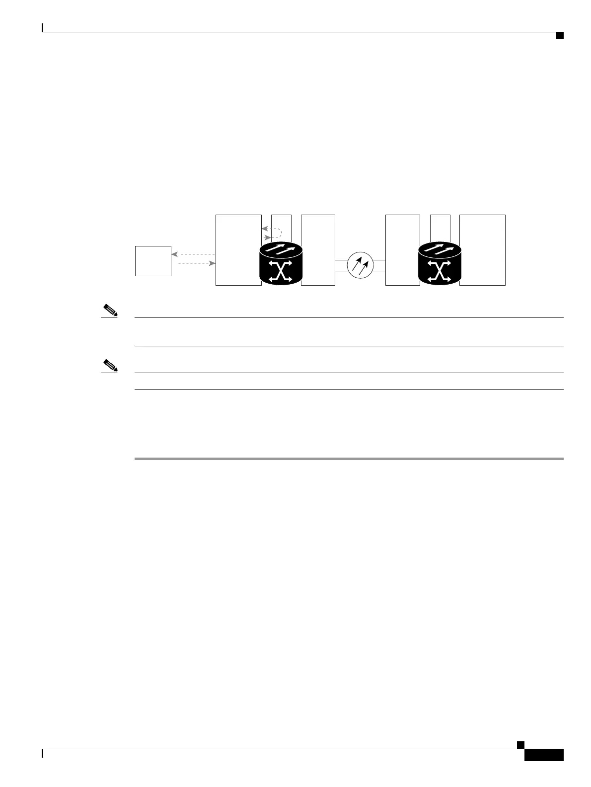
The hairpin test is performed on the cross-connect card in the network circuit. A hairpin circuit uses the
same port for both source and destination. Completing a successful hairpin through the port isolates the
possibility that the cross-connect card is the cause of the faulty circuit. Figure 1-32 shows an example
of a hairpin loopback on a source-node port.
Figure 1-32 Hairpin on a Source-Node Ethernet Port
Note The ONS 15454 does not support simplex operation on the cross-connect card. Two cross-connect cards
of the same type must be installed for each node.
Note Hairpin loopbacks require on-site personnel.
Complete the “Create the Hairpin Circuit on the Source-Node Ethernet Port” procedure on page 1-75.
Create the Hairpin Circuit on the Source-Node Ethernet Port
Step 1 Connect an Ethernet test set to the port you are testing:
a. If you just completed the “1.5.2 Perform a Terminal Loopback on a Source-Node Ethernet Port”
procedure on page 1-71, leave the Ethernet test set hooked up to the Ethernet port in the source node.
b. If you are starting the current procedure without the Ethernet test set hooked up to the Ethernet port,
use appropriate cabling to connect the Ethernet test set to the port you are testing.
Step 2 Adjust the test set accordingly. (Refer to manufacturer instructions for test-set use.)
Step 3 Use CTC to set up the hairpin circuit on the test port:
a. In node view, click the Circuits tab and click Create.
b. In the Circuit Creation dialog box, choose the type, such as STS, and number, such as 1.
c. Click Next.
d. In the next Circuit Creation dialog box, give the circuit an easily identifiable name such as Hairpin1.
e. Choose the Size, such as STS-1.
f. Uncheck the Bidirectional check box. Leave the default values for State, SD Threshold, and
SF Threshold.
g. Click Next.
Source
ONS Node
Destination
ONS Node
159521
OC-N CE-MR-10XCOC-N
Test Set
XCCE-MR-10