DMD1050TS Satellite Modem Board
Revision 1
Theory of Operation 3–1 MN-DMD1050TS
Chapter 3. Theory of Operation
3.1 DMD1050TS Hardware
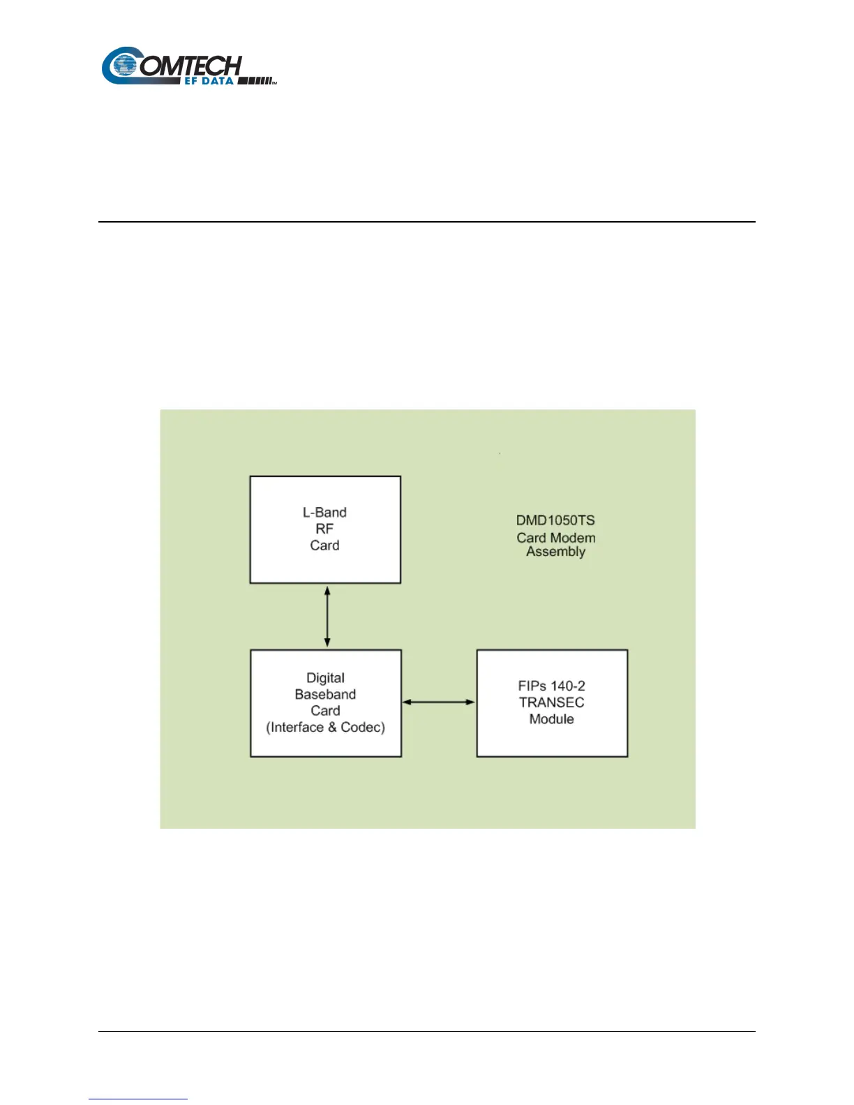
The DMD1050TS uses three printed circuit cards in its design. The standard configuration
consists of:
• L-Band Assembly
• Digital Baseband Assembly
• FIPs 140-2 TRANSEC Security module
This configuration includes built in data interfaces and several software upgrade options.
A block diagram of the DMD1050TS is shown in Figure 3-1.
Figure 3-1. DMD1050TS Block Diagram