Operator’s Manual: Standard 360a Model Y (360y) Label Applicator
30
Tamp Applicator Setup
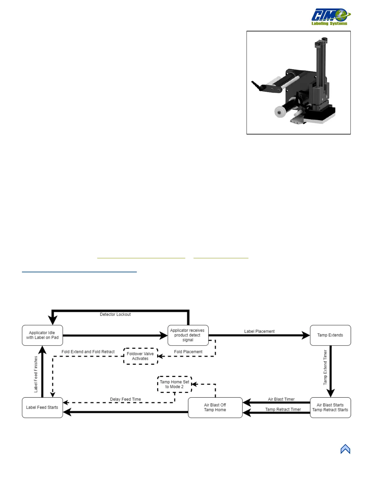
The Tamp applicator nose assembly [81] consists of a tamp slide, label manifold, and a
label pad. The label is fed out onto the label pad and is tamped within
1
/
8
in. of the
labeling surface. The label is then blown off by an air blast. The tamp applicator has
higher placement accuracy and is less dependent on product movement.
Starting at the Main Menu, tap Setup Menu > Setup Passcode > Configuration
Menu > Top Right-Hand Corner > Special Options Passcode > Apply Mode
and tap the Up or Down arrow to choose one of the following types of tamping action:
• Normal Tamp: A label feeds out onto the label pad and the applicator waits for
a product detect signal to tamp and apply the label. After applying the label, the
tamp pad returns home to receive another label.
• ITB Tamp: A label feeds out onto the label pad and the tamp extends. The
applicator waits for a product detect signal before applying the label via an air
blast and returning home to receive another label.
• DAT Tamp: The dual action tamp has a swing action to apply a label to the leading or trailing panel of the product and a
linear tamp action to apply a label to a side panel of the product. The DAT applicator has three (3) modes of operation:
o Swing first then tamp (Leading)
o Tamp first then swing (Trailing)
o Inverted swing then inverted tamp (Inverted).
o Within all modes, a swing only and a side only option is available.
• Corner Wrap: The label feeds out onto the label pad and the applicator waits for the product detect signal to apply a label to
the front panel and then around the corner to the side panel. This applicator type must be used with a Hi/Lo pressure valve
bank so that the product can push through the extended swing arm.
If selecting Normal Tamp or ITB tamp, use the setup guides in the sections listed below to set up tamp application. If selecting DAT
or corner wrap continue to the Dual Action Tamp (DAT) Setup or Corner Wrap Setup
sections of the manual.
Normal Tamp Flow Chart
Figure [82] represents the cycle of a normal tamp applicator. Some cycle-affecting options are depicted by dotted lines. Any step that
has multiple arrows leading to it indicates that multiple steps must be complete prior to advancing. Not all options are shown as not all
options effect the cycle.
NOTE: Use of Tamp Home and Tamp Return sensors will override the settings of the Tamp Extend and Tamp Retract timers.
[80] Tamp Nose Assembly (Right Hand)
[81] Normal Tamp Assembly Flow Chart