Maintenance Manual: Standard 360a Model Y (360y) Label Applicator
13
Wiring Changeover
1. Remove the zip ties holding the AC power wiring and the label sensor fiber
optic cable to the adhesive pads near the wiring entry points.
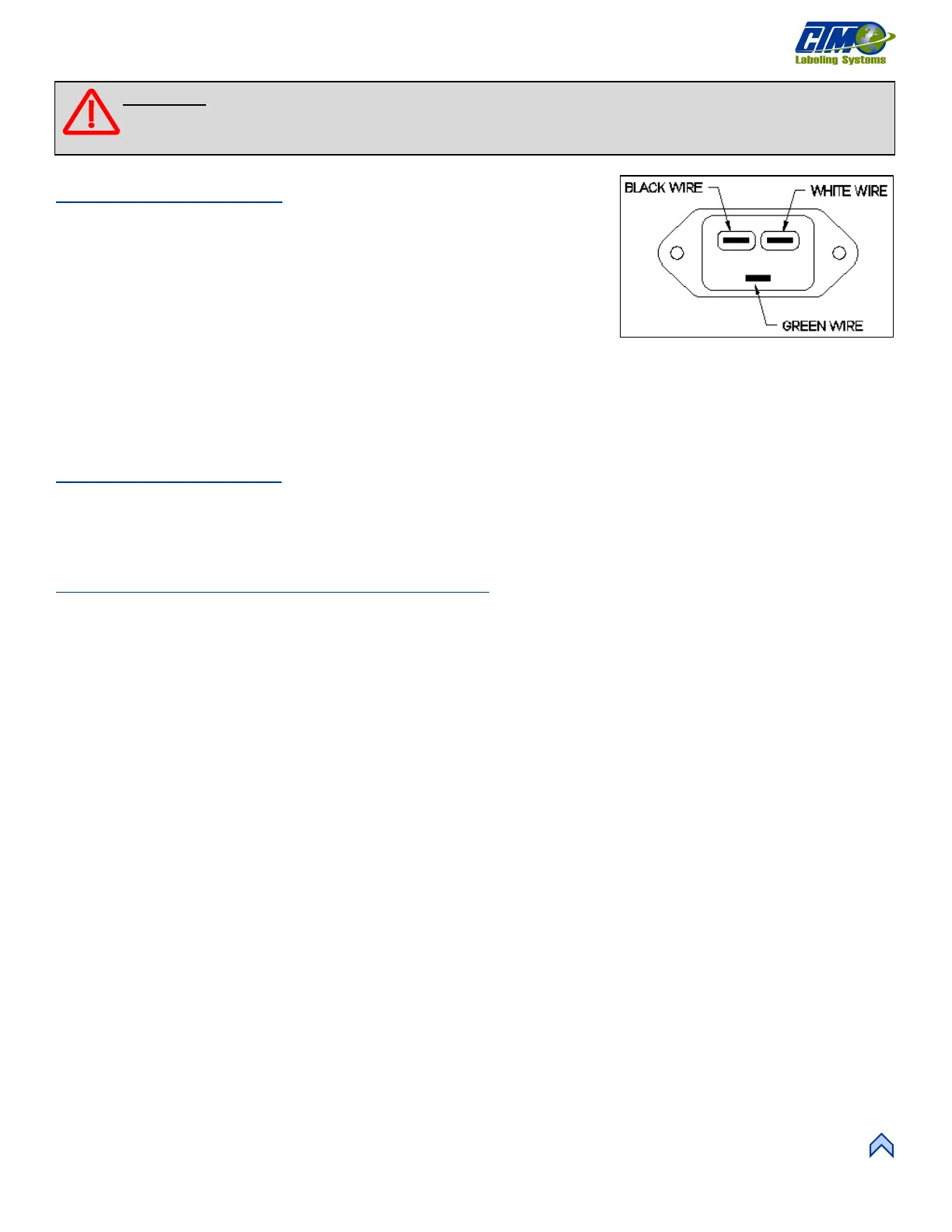
2. Remove the fast-on terminal connections at the fuse holder and the AC power
entry module.
3. Cut the tie-wraps securing the blow box fan connector to the bolt-on zip tie
mounts and move the connector to the opposite side of the machine. Secure
the connector in place with the open end towards the side frame.
4. Move wiring to the opposite side of the applicator and neatly zip tie in place.
5. Swap the AC power entry module and the fuse holder with the fiber optic plate and the fuse holder plug.
6. Re-connect the terminals for the fuse holder and the AC power entry module.
NOTE: All wiring comes from the factory long enough to be wired either left or right hand.
Rewind Installation
1. Attach the rewind mounting plate to the housing using the six #10 screws.
2. Install the rewind mandrel on the mandrel drive shaft.
3. Install the belt connecting the rewind clutch to the motor.
Blow Box Nose Assembly Installation
1. Ensure that the peel edge assembly is removed from the blow box nose assembly.
2. Install the blow box nose assembly using the six #10 mounting screws making sure that the fan harness is tucked inside the
applicator housing.
3. Plug the blow box fan harness into its connector on the underside of the electronic shelf.
4. Install the peel edge assembly using the two ¼ in. screws and the peel edge nut.
5. Ensure the label sensor is installed in the peel edge with the optical fibers running through the two holes in the peel edge side
frame. Run the optical fibers through the two holes in the mounting plate.
6. Re-connect the fiber optic cable to the label sensor located on top of the power supply.
a. Open the top cover on the sensor and slide the cinching mechanism located on the right side of the sensor housing
upward.
b. Plug the emitter fiber (from the lower fork in the label sensor) into the outgoing arrow connection on the sensor
housing and the detector (from the upper fork in the sensor) to the incoming arrow connection.
c. Slide the cinching mechanism downward and close the top cover on the sensor.
7. Neatly zip tie any excess fiber optic cable to the adhesive pads located near the fiber mounting plate.
NOTE: The excess fiber should be formed into a loop greater than 3in. in diameter to avoid kinking the fiber.
8. Install the air tubes interconnecting the two sides of the applicator.
9. Replace the stainless-steel housing cover.
[26] Power Entry Module Wiring
(Looking into the Backside)
WARNING: Disconnect air and power to the applicator BEFORE performing the following procedures. Injury
from moving parts and/or electrical shock may occur.