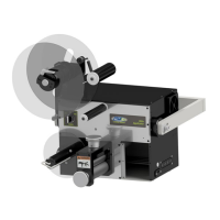
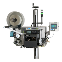
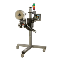
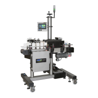
Operator’s Manual: Standard 360a Model Y (360y) Label Applicator
32
Tamp Air Assist Tube Setup
The air assist tube blows a stream of air onto the label to push it against the tamp pad during the label feed. The air assist starts to blow
when the web starts to move and stops when the label is on the pad. The air assist time allows the air assist to blow after the label feed
to help stabilize the label.
1. Adjust the air assist tube by loosening the screw directly beside it so it’s blowing in the center of label. Ensure that the label
feeds out against the label pad.
2. Adjust the regulator for the air assist located on the valve bank by turning the knob right above the valve that says Assist, to
between 30-40PSI. This is a typical setting, but it may be changed as needed.
3. If a longer air assist is needed to help position the label, from the Main Menu tap Setup Menu > Applicator Setup
Menu > Web Speed > Ext Air Assist and enter a value between .000sec.-1sec.
Tamp Air Blast Setup
The air blast transfers the label from the label pad to the product and is a function of time and air pressure.
1. Set the regulator for the air blast between 40 PSI–50 PSI by turning the knob above the valve on the valve bank that says
Assist.
2. If the air blast time needs changed adjust the air blast variable by tapping Setup Menu > Applicator Setup > Web
Speed > Air Blast and enter a value between .005sec. – 1sec.
Tamp Slide Setup
The tamp slide moves the label pad and manifold toward the product. Its speed is a function of air pressure and airflow. The valve and
regulator for the tamp assembly are part of the valve bank mounted to the side of the applicator.
1. Set the regulator between 40 PSI and 50 PSI, but it may be changed, as necessary.
2. Two adjustment knobs (flow controls) are provided on the air cylinder to adjust the tamp extend and retract speed.
a. Turn the knobs clockwise to slow the movement of the cylinder.
b. Turn the knobs counterclockwise to speed up the cylinder.
NOTE: The tamp extend and retract times must be setup by the operator since they are dependent on the setting of the adjustment
knobs. Both timers are in the Applicator Setup Menu of the display.
Tamp Extend Time
Tamp Extend Time is the time allotted to fully extend the tamp slide assembly. After the tamp extend time elapses, an air blast forces
the label off the label pad onto the product. To keep cycle time low, set the extend time so that the air blast occurs when the slide
reaches the fully extended position.
To change the tamp extend time, ensure that the flow controls are properly set up. From the Main Menu, tap Setup Menu >
Configuration Menu > Application Setup and enter a value under Tamp Extend between .01sec. – 5sec.
Tamp Retract Time
The tamp retract time is the time allotted to fully retract the tamp slide assembly. At the end of the tamp retract time, a label is fed out
onto the pad. Too small of a value causes a label to feed out before the label pad is in the home position. Too high of a value increases
cycle time.
To change the tamp retract time, start at the Main Menu, tap Setup Menu > Configuration Menu > Application Setup and
enter a value for Tamp Retract between .01-5 seconds.
NOTE: If tamp switches are used, only set both tamp extend and retract times to a value higher than the time required. The tamp
switches overrides any excess time.