Maintenance Manual: Standard 360a Model Y (360y) Label Applicator
9
CHANGING DISPENSE HAND
When performing an applicator changeover, the nose assembly, unwind assembly, rewind, and wiring are first changed to the opposite
hand dispense. Then each component assembly is remounted on the opposite side of the applicator. The symmetry of the applicator
main module and the individual parts facilitate the changeover process, but it can be confusing if care is not exercised. The
explanation and diagrams in the sections below will guide you through this process.
Applicator Changeover Sequence
Reference the below sections to accurately complete the Applicator Changeover Sequence.
1. Remove the nose assembly.
2. Change the applicator nose assembly to the opposite hand dispense.
3. Remove the rewind assembly from the applicator.
4. Change the rewind assembly to the opposite hand dispense.
5. Change the wiring to the opposite side of the applicator.
6. Change the unwind assembly to the opposite hand dispense.
7. If the applicator is a Tamp or Air Blow, move the valve assembly to the opposite side of the machine.
8. Install the rewind assembly on the opposite side of the machine.
9. Install the nose assembly on the opposite side of the machine.
Nose Assembly Removal
The following steps detail the removal of the various nose assemblies available for the 360y. Locate the assembly pertaining to the
nose on your applicator and follow the steps.
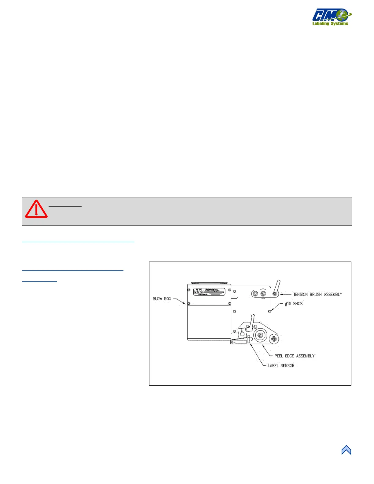
Blow Box Nose Assembly
Removal
1. Remove the stainless-steel cover from
the bottom of the Blow Box.
2. Remove the air tubes interconnecting
the two sides of the applicator.
3. Disconnect the fiber optic cables from
the label sensor mounted on top of the
power supply.
4. Open the top cover on the sensor and
slide the cinching mechanism located
on the right side of the sensor housing
upward. Gently remove the two fiber
cables from the sensor.
5. Cut the zip ties securing the bolt-on zip
tie mounts and gently pull the fiber
optic cable out of the wiring clamps and through the holes in the fiber optic mounting plate.
6. Unplug the blow box fan connector located on the underside of the electronic shelf and disconnect the hoses for the air assist
tube and the air blast manifold at the applicator housing.
7. Remove the peel edge assembly to gain access to the #10 mounting screws and remove the screws holding the nose assembly
to the housing.
[18] Blow Box Nose Assembly
WARNING: Disconnect air and power to the applicator BEFORE performing the following procedures. Injury
from moving parts and/or electrical shock may occur.