Operator’s Manual: Standard 360a Model Y (360y) Label Applicator
36
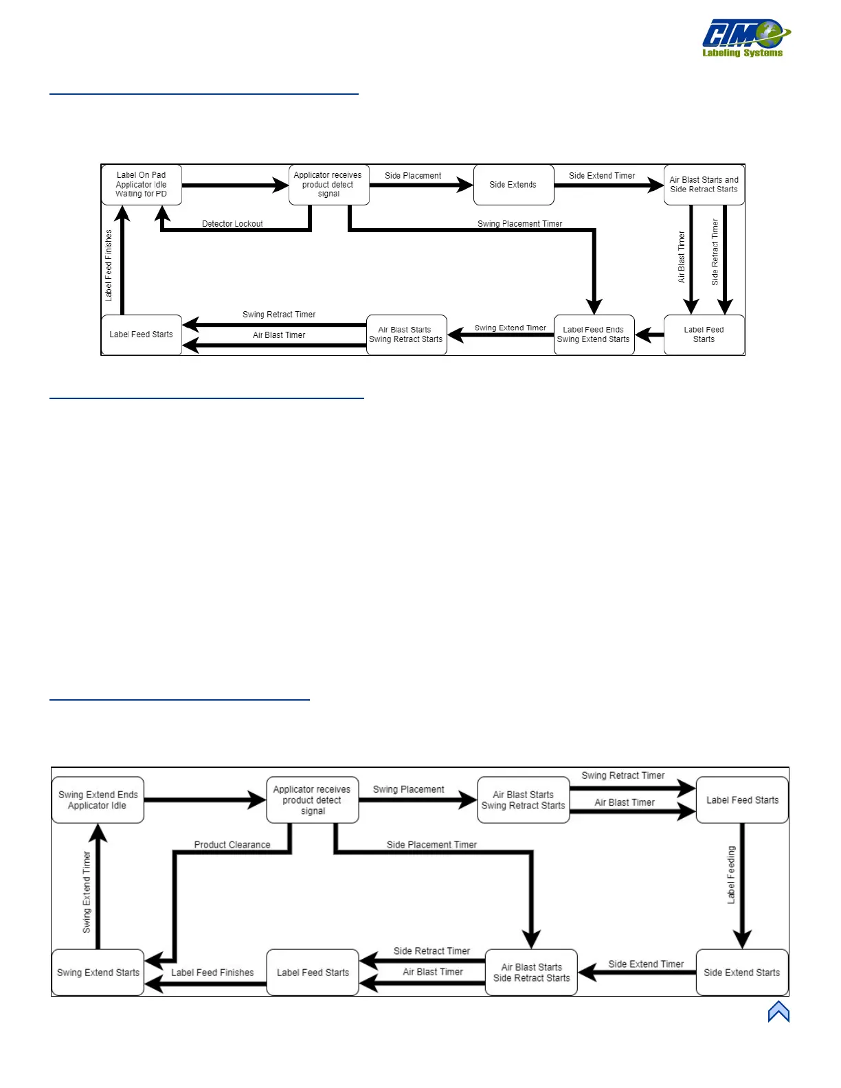
DAT: Trailing Edge Flow Chart
Figure [87] depicts the cycle of a DAT set to trailing edge. Any step that has multiple arrows into it means the timer / distances run
concurrently and must all be complete before continuing.
NOTE: If tamp / swing home and retract sensors are installed they will override the tamp / swing home / retract timers.
DAT: Inverted Mode Sequence
1. The applicator is online, and a label is on the pad.
2. The label pad swings into product flow and waits for the product detect signal.
3. Once the product detect signal is received, the applicator starts the product clearance and side label placement times or
distances while it waits the swing label placement time or distance.
4. When the swing label placement is finished, the applicator blows the label off the pad and onto the front of the product. At
the same time, the label pad swings home and the retract timer starts.
5. At the end of the swing retract time, another label feeds out onto the pad and the tamp valve turns on, moving the label pad to
the side of the product.
6. The tamp extend timer starts and when complete, the applicator waits for the side label placement to finish.
7. When both are done, the label is blown onto the side of the product and the tamp valve turns off causing the label pad to
retract.
8. The tamp retract time starts and at the end, another label feeds out onto the pad.
9. The applicator waits for the product clearance time or distance to finish, and the label pad swings back out into product flow,
ready to start the sequence again.
DAT: Inverted Flow Chart
Figure [88] depicts the cycle of a DAT set to inverted. Any step that has multiple arrows into it means the timer/distances run
concurrently and must all be complete before continuing.
NOTE: If tamp/swing home and retract sensors are installed they will override the tamp / swing home / retract timers.
[86] DAT Trailing Wdge Flow Chart
[87] DAT Inverted Flow Chart