Operator’s Manual: Standard 360a Model Y (360y) Label Applicator
31
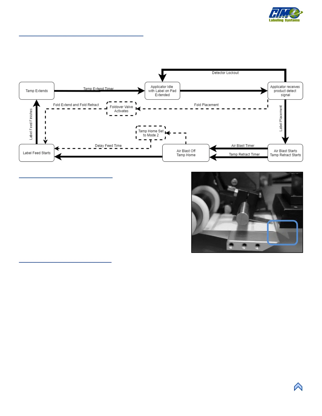
Inverted Tamp (ITB) Flow Chart
Figure [83] represents the cycle of an inverted tamp applicator. Some cycle-affecting options are depicted by dotted lines. Any step
that has multiple arrows leading to it indicates that multiple steps must be complete prior to advancing. Not all options are shown as
not all options effect the cycle.
NOTE: Using Tamp Home and Tamp Return sensors overrides the settings of the Tamp Extend and Tamp Retract timers.
Tamp Peel Edge Alignment
1. Power-on the applicator, connect it to air, and disable it.
2. Advance the web by hand by turning the drive roller and stop when
half of the label is off the peel edge tip. The label should be at an
angle 5°-15° from the label pad surface [84]. The stiffer the label, the
flatter the angle should be.
3. Adjust the peel edge by loosening the (2) ¼ in. socket head screws on
the peel edge faceplate. Move the assembly close to the tamp pad.
4. Allow
1
/
16
in. clearance distance between the peel edge and tamp
assembly.
5. Repeat Step 2 to check label angle and re-adjust if needed.
Tamp Vacuum Pressure
• The tamp pad vacuum is generated by a vacuum venturi located on the applicator’s valve bank.
• The vacuum is used to hold the label on the label pad until the air blast releases it. Too much or too little vacuum affects label
placement on the pad.
• The vacuum can be adjusted by changing the air pressure to the vacuum regulator feeding the venturi, which is typically set
to 20 PSI, but it can be changed as needed. To adjust, turn the knob above the vacuum valve that says Vacuum.
• If the label is fluttering during label feed, it may be due to too high vacuum pressure.
NOTE: It is important to match label size with the label pad size so that no holes are uncovered when the label is on the pad. This
may result in losing vacuum.
[82] Inverted Tamp Blow Assembly Flow Chart