User Interface
152
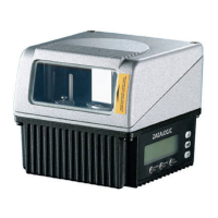
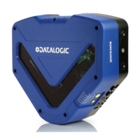
DX8210 Barcode Scanner
Aux (Input 3) Active Level
Select Active Closed or Active Open from the drop-down list.
Active Closed: Input 3 is active when current flows through IN3 pins.
Active Open: Input 3 is active when there is no current flowing through IN3
pins.
I/O (Input 4) Active Level
Select Active Closed or Active Open from the drop-down list.
Active Closed: Input 4 is active when current flows through IN3 pins.
Active Open: Input 4 is active when there is no current flowing through IN3
pins.
Digital Output Lines
Select Digital Output Number to View/Modify.
Select the number of the output you will view or modify from the drop-down list.
Digital Output n
Digital Output n Use
Select Local, EthernetIP, Profibus/Profinet, or Redundancy from the drop-down list.
This parameter selects the source that drives the digital output. Local output is
driven by the device application program. EithernetIP is driven by the EtherNet/IP
Host and Profibus/Profinet is driven by the relative Fieldbus Host.
Digital Output n Line State
Select Normally Open or Normally Closed from the drop-down list.
Each output can be represented with an NPN transistor; this transistor acts like a
switch: so, when the transistor is OFF, it acts like an OPEN switch. On the contrary,
when the transistor is ON, it acts like a CLOSED switch.
Normally Open: The idle state of the output line is open, that is, the NPN
transistor is OFF (like an open switch).When the output is activated, the
transistor goes ON (like a closed switch).
Normally Closed: The idle state of the output line is closed, that is, the NPN
transistor is ON (like a closed switch).When the output is activated, the
transistor goes OFF (like an open switch).
Activation
Primary Activation Event And Secondary Activation Event
Select a Primary Activation Event from the drop-down list.
None: The output is always in line state.
Complete Read: The event occurs, if all selected codes are read.
Partial Read: The event occurs, if less than the selected codes are read.
No Read: The event occurs, if no code is read.
Trigger On: The event occurs, when a start event takes place starting the
reading phase.
Trigger Off: The event occurs, when a stop event takes place ending the
reading phase.
Multiple Read: The event occurs, if a code is read more than once
consecutively.
Right/Match: The event occurs, if a code is successfully decoded and matches
the Match Code
(Verifier Code).
Wrong/No Match: The event occurs, if a code is successfully decoded but
does not match the Match Code
(Verifier Code).
Activate On Error
Select Disable or Enable from the drop-down list. If this parameter is enabled, the
output will activate when a diagnostic error message is sent.
Deactivation
Primary Deactivation Event
Select a Primary Deactivation Event from the drop-down list.
This parameter setting is not valid, if the input has already been defined in On Line or
PackTrack™ Operating Modes“Operating Mode” on page 52.
This parameter setting is not valid, if the input has already been defined in On Line or
PackTrack™ Operating Modes. See “Operating Mode” on page 52.
When using this parameter, all other activation events should be set to None.
 Loading...
