Introduction
12 Gryphon™ I GD4132/GM4102/GBT4102
The BC40xx™ Radio Base
Base LEDs
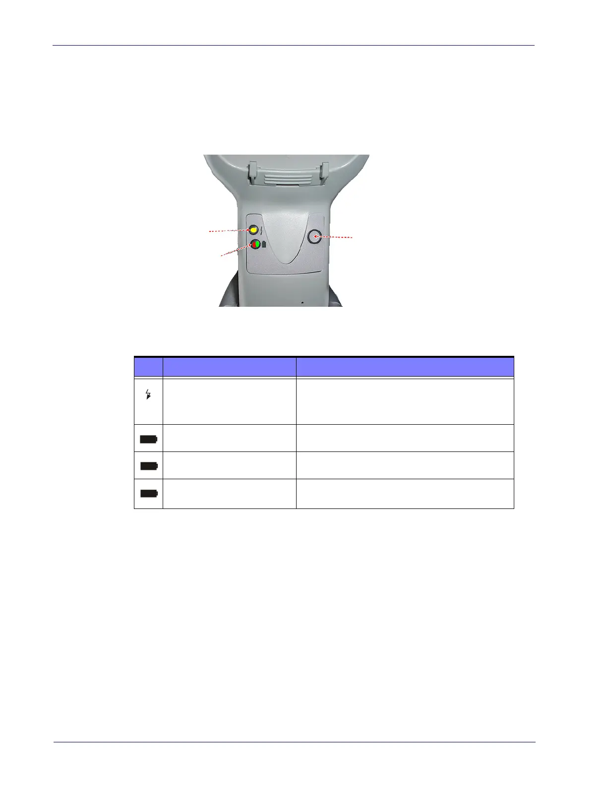
LEDs on the Gryphon I Base provide information about the Base’s status, as
shown in Figure 1.
Figure 1
YELLOW LED
RED LED /
GREEN LED
BUTTON
. Gryphon I Base LEDs
The following table describes the significance of each LED:
LED STATUS
Power on / Data
Yellow On = Base is powered
Yellow Blinking = Base receives data and
commands from the Host or the Reader.
Charging Red On = Battery charging is in progress.
Charge completed Green On = the Battery is completely charged.
Charging + Charge completed
Red and Green Blinking together = the Reader is
n
ot correctly placed onto the Base.
See "Base Station Indications (Cordless Models ONLY)" on page 347 for more
specific details on the LEDs.
Base Button
The Base contains a button which is used primarily to perform a paging func-
tion. Pressing the button causes a sound signal to be emitted by all scanners
li
nked with this Base, as long as the scanner is awake (see "P
owerdown Time-
out" on page 268) and reception is enabled (see "Sl
eep Mode Timeout" on page
98). The button can also be used to "fo
rce device connection" via the Datalogic
Aladdin Software tool (available for free download from the Datalogic website).
See
the Aladdin Online Help for details.
See "Base Station Indications (Cordless Models ONLY)" on page 347 for further
information on Base Button functions.

 Loading...