Chapter 4 Connect the Front End
100 Storage Center SC8000 Controller Deployment Guide
Example Legacy Mode Configuration
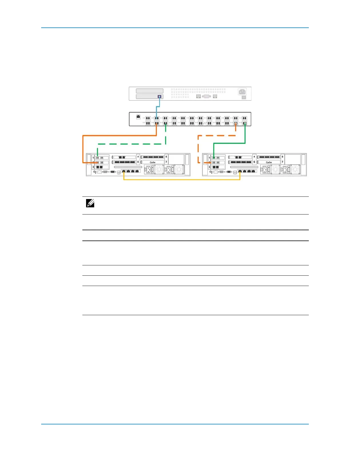
Thefollowingfigureshowsadual‐controllerStorageCenterinlegacymodeconnectedto
aFibreChannelserverwithtwofaultdomains.Faultdomain1(showninorange)is
comprisedofprimaryportP1oncontrollerAandreservedportR1oncontrollerB.Fault
domain2(showningreen)is
comprisedofprimaryportP2oncontrollerBandreserved
portR2oncontrollerA.
Figure 89. Legacy Mode Example with FC
Thefollowingtablesummarizesthefailoverbehaviorsforthisconfiguration.
Note: Tousemultiplepathssimultaneously,theservermustbeconfiguredtouse
MPIO.
Scenario Failover Behavior
Normaloperatingconditions • PrimaryportsP1andP2(bothfaultdomains)passIO.
• ReservedportsR1andR2remaininastandbymodeuntila
controllerfailure.
ControllerAfails Infaultdomain1,primaryportP1failsovertoreservedportR1.
ControllerBfails Infaultdomain2,primaryportP2failsover
toreservedportR2.
Asingleportfails Theportdoesnotfailoverbecausetherewasnocontrollerfailure.If
asecondpathisavailable,MPIOsoftwareontheserverprovides
faulttolerancebysendingIOtothefunctioningportintheother
faultdomain.
Controller A
FC Switch
Server
Controller B
Primary Port — P2
Primary Port — P1
Reserved Port — R1
Reserved Port — R2