Chapter 1 Introduction
10 Storage Center SC8000 Controller Deployment Guide
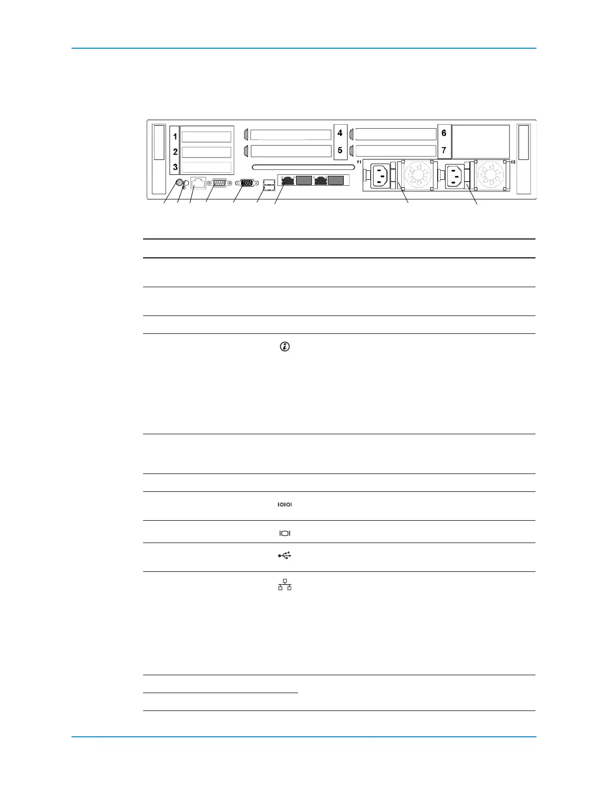
SC8000 Back-Panel Features and Indicators
ThebackpanelofthecontrollercontainsIOcardslots,asystemidentificationbutton,
connectors,andpowersupplies.
Figure 6. SC8000 Controller Back View
Item Name Icon Description
Slots1–3 Low‐profileIOcard
slots
—Portsarenumberedbeginningwithport1ontheleft.
Slots4–6 Full‐heightIOcard
slots
—Portsarenumberedbeginningwithport1ontheright.
Slot7Cachecardslot — Hoststhecachecard.
1System
identification
button
Usedtolocateaparticularcontrollerwithinarack.Whena
System
IDbuttononthefrontorbackpanelispressed,the
frontLCDpanelandthebacksystemstatusindicatorflash
untiloneofthebuttonsispressedagain.
•PresstotogglethesystemIDonandoff.
•IfthecontrollerstopsrespondingduringPOST,press
andholdthesystemIDbuttonformorethanfive
secondstoenterBIOSprogressmode.
2System
identification
connector
— Connectstheoptionalsystemstatusindicatorassembly
throughtheoptionalcablemanagementarm.
3 iDRAC — ConnectstotheEthernetswitchintherack.
4Serialport Allowsyoutoconnecttothecontrollerusingaserial
interface.
5Videoconnector Allowsyoutoconnecta
VGAmonitortothecontroller.
6USBconnectors AllowsyoutoconnectUSBdevicestothecontroller.The
portsareUSB2.0‐compliant.
7Embedded
Ethernetconnectors
ConnectsthecontrollertotheEthernetswitchandtoother
controllersintherack.Theportsfunctionasfollows:
• Port1:ETH1‐10GbEcapable,configuredfor1GbE
(Connect
tosecondcontrollerforIPC).
• Port0:ETH0‐1GbE(ConnectstotheEthernetswitchfor
systemlogin,email,alerts,SNMPtraps,PhoneHome
data,andaccessforsoftware).
Note: Ports2and3arenotused.
8PowerSupply1—Hot‐swappable,750WAC
100‐240VAC,auto‐ranging,50/60Hz.
9PowerSupply
2—
435768
IPC
9
IO card
2
1
IO card
1302
cache card
IO card
IO card
IO card
MGMT
IO card