6
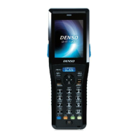
BHT-1300B Series
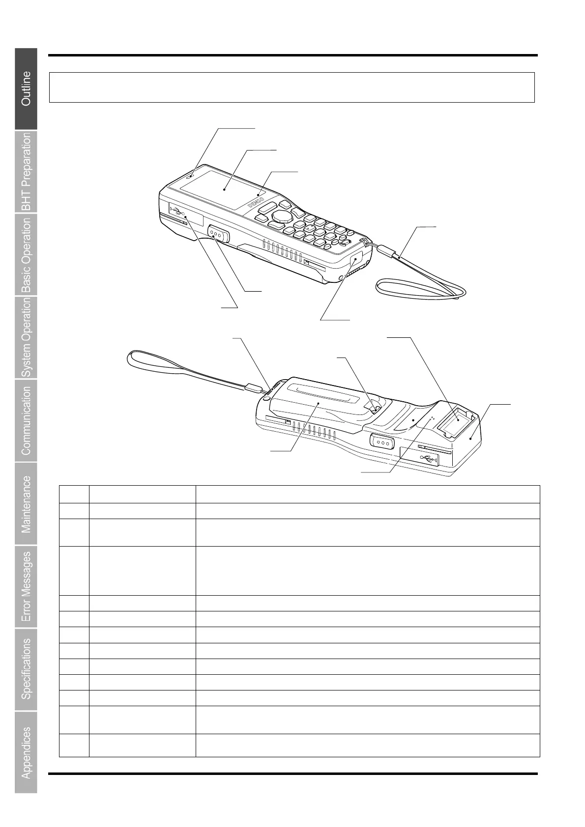
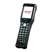
1.2 Components and Functions
1.2.1 BHT Front/Rear
No. Name Function and Description
(1) LCD (Liquid crystal display) Displays the characters and graphic patterns.
(2) Indicator LED Indicates the code read status.
Illuminates in blue when the BHT has successfully read a code.
(3)
Trigger switches
(M3 and M4 Magic keys)
Press this when scanning a code.
The SF and ENT key functions can be assigned to these magic keys by making settings at the
SYSTEM MENU. Character strings can be assigned at user programs.
Refer to Chapter 4 “System Operation” for details on how to operate the SYSTEM MENU.
(4) USB connector cover
Open this when connecting the USB cable.
(5) Speaker Emits sound.
(6) IrDA interface port Used to exchange data/programs with the optical communication unit CU-1300 or other BHTs.
(7) Hand strap Be sure to put your hand through this strap to prevent you from dropping the BHT accidentally.
(8) Battery cover Remove this cover to replace the battery cartridge.
(9) Battery cover lock Used to lock or unlock the battery cover.
(10) Code reading window Align the reading window with codes to perform code reading.
(11) Charging/communication
terminal
Used to communicate and charge the BHT that is set on the CU.
(12)
Wireless LAN / Bluetooth
®
communication antennas
Used to communicate with the wireless LAN access point and the Bluetooth device.
(2)
(1)
(3)
(4)
(5)
(6)
(8)
(7)
(9)
(10)(11)
(12)
(3)