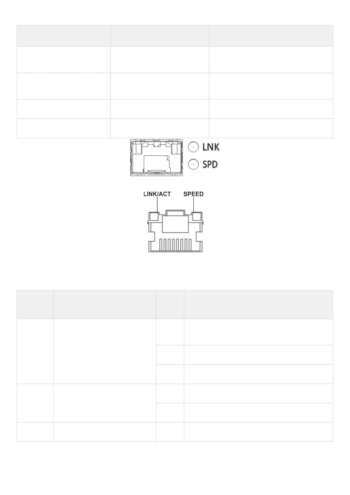
SPEED indicator is lit LINK/ACT indicator is lit Ethernet interface state
Off Off The port is disabled or connection is not
established.
Off Solid on 10Mbps or 100Mbps connection is
established.
Solid on Solid on 1000 Mbps connection is established.
X Flashes Data transfer is in progress.
Figure 46 – Location of SFP connector indicators
Figure 47 – Location of RJ-45 connector indicators
The following table lists description of system indicator statuses and meanings.
Table 38 – Status of system indicators
Indicator
name
Indicator function LED
State
Device State
Power Device power LED. Green Device power is OK. Main power supply, if installed, is
operational. The main software is uploaded.
Red The main software is not loaded.
Off Device internal power supply failure.
Status Current device status LED. Green Device is in normal operation state.
Orange Device is booting up the software.
Alarm Alarm LED. - -

 Loading...
