14.2.2 Configuration example
Objective:
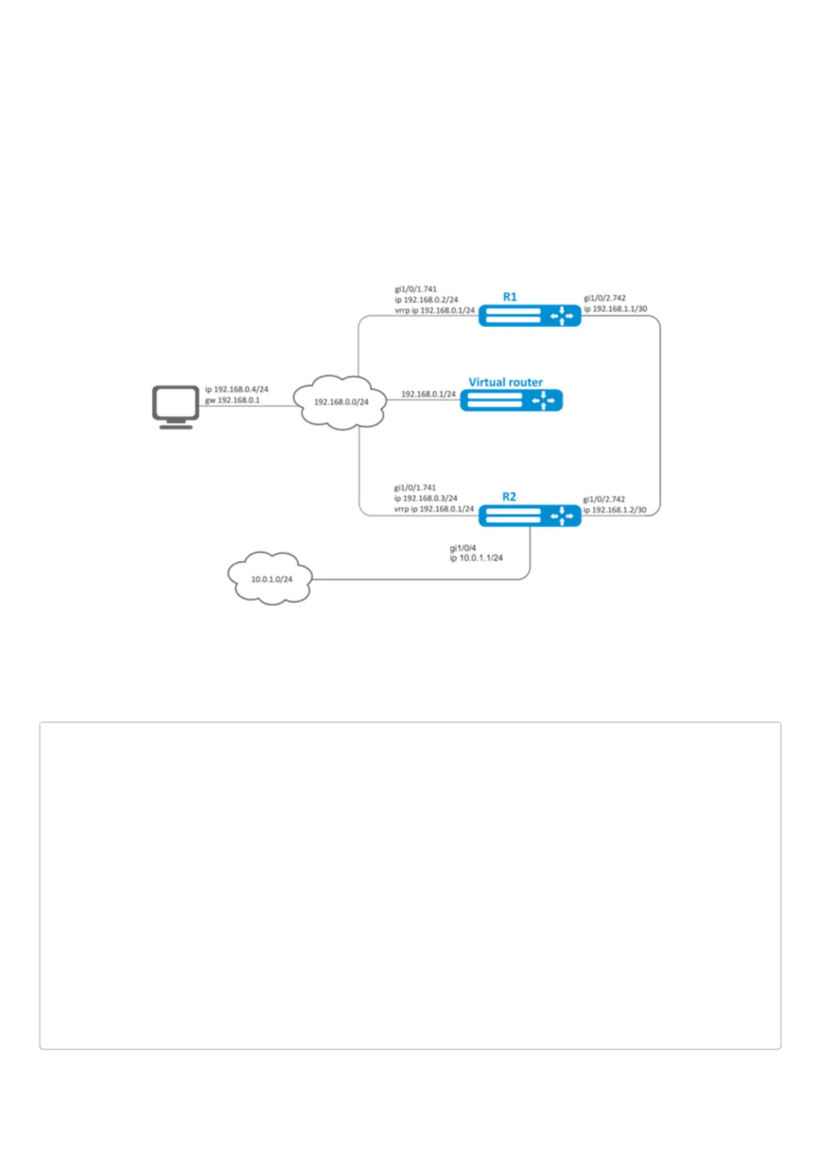
Virtual gateway 192.168.0.1/24 is organized for 192.168.0.0/24 subnet, using VRRP protocol and routers R1
and R2. There is a link with a singular subnet 192.168.1.0/30 between R1 and R2 routers. Subnet 10.0.1.0/24 is
terminated only on R2 router. PC has IP address - 192.168.0.4/24 and default gateway 192.168.1.1.
When router R1 is in vrrp backup state, traffic from PC will be transmitted without any additional settings.
When router R1 is in vrrp master state, additional route is necessary for subnet 10.0.1.0/24 through interface
192.168.1.2.
Initial configurations of the routers:
1 R1 router
hostname R1
interface gigabitethernet 1/0/1
switchport forbidden default-vlan
exit
interface gigabitethernet 1/0/1.741
ip firewall disable
ip address 192.168.0.2/24
vrrp id 10
vrrp ip 192.168.0.1/24
vrrp
exit
interface gigabitethernet 1/0/2
switchport forbidden default-vlan
exit
interface gigabitethernet 1/0/2.742
ip firewall disable
ip address 192.168.1.1/30
exit

 Loading...
