2.4 Design
This section describes the design of the device. Depicted front, rear, and side panels of the device, connectors,
LED indicators and controls.
The device has a metal housing available for 19” form-factor rack mount; housing size is 1U.
2.4.1 ESR-1700 design
ESR-1700 front panel
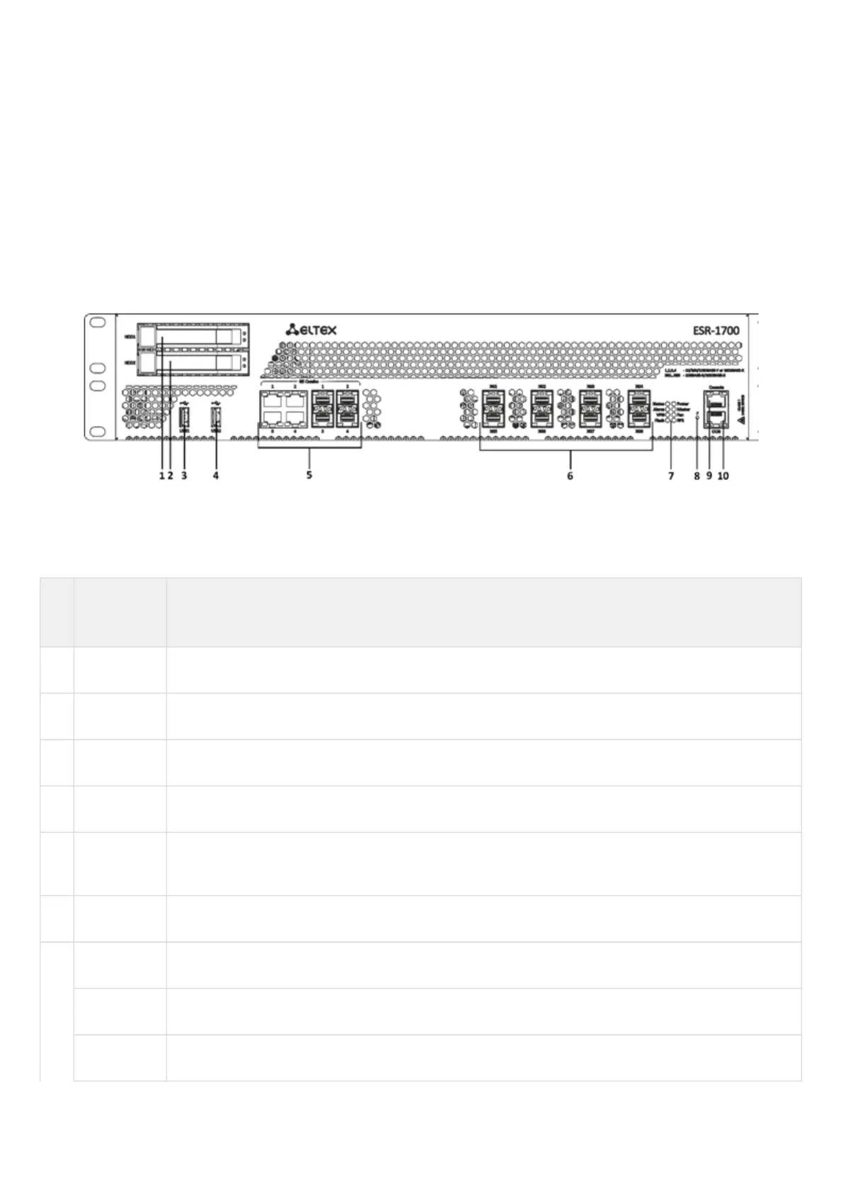
The front panel layout is depicted in figure 1.
Figure 1 – ESR-1700 front panel
Table 9 lists connectors, LEDs and controls located on the front panel of ESR-1700.
Table 9 – Description of ESR-1700 connectors, LEDs and front panel controls
№ Front panel
element
Description
1 HDD1 Connector for HDD installation.
2 HDD2 Connector for HDD installation.
3 USB1 Port for USB device connection.
4 USB2 Port for USB device connection.
5 Combo
Ports [1 .. 4]
4 ports of Gigabit Ethernet 10/100/1000BASE-X (SFP).
6 XG1 – XG8 Slots for 10G SFP+/1G SFP transceivers.
7 Status Current device status LED.
Alarm Alarm LED.
VPN VPN gateway operation mode LED (is not supported in the current version).

 Loading...
