№ Top
panel
elemen
t
Description
2 - The LED is not used
3 USB1,
USB2
External USB devices LED
4 [1 .. 4] Ethernet ports LED
5 [5 .. 6] Optical interfaces LED
2.4.11 Light Indication
ESR-1700, ESR-1511, ESR-1500, ESR-1200, ESR-1000 light indication
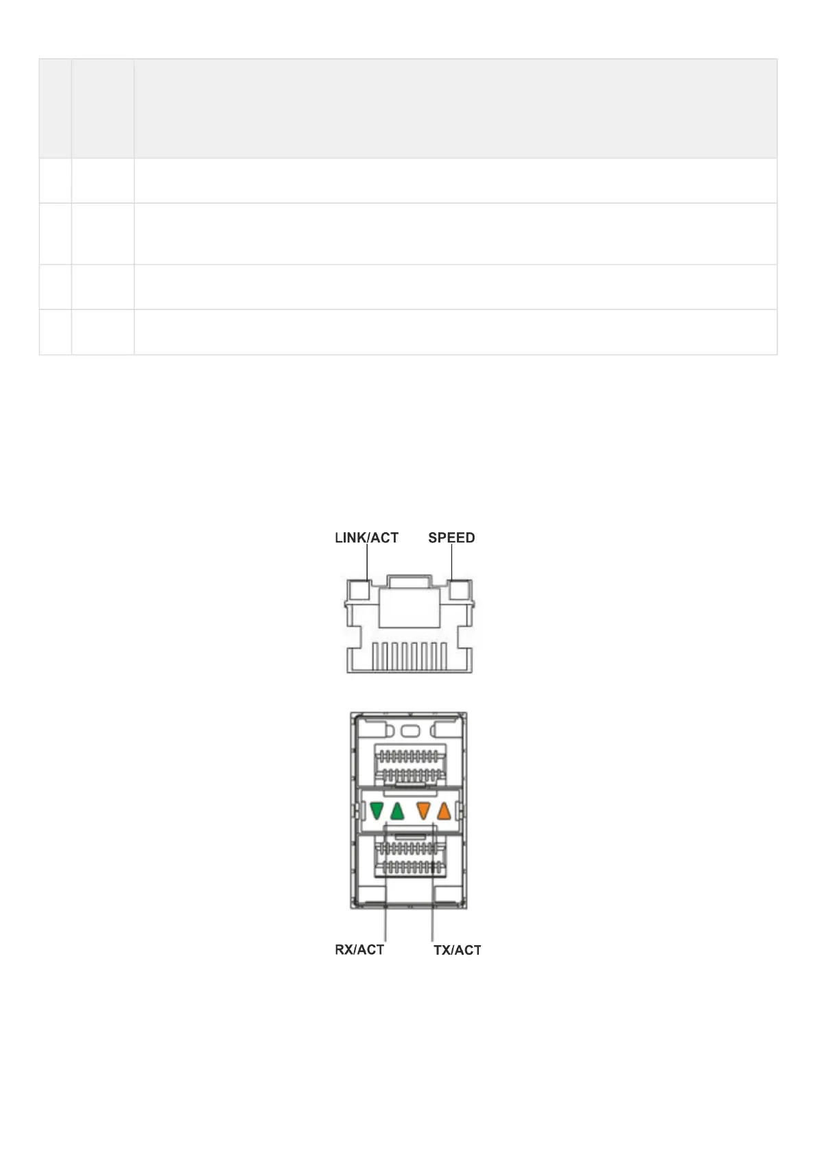
Gigabit Ethernet copper interface statuses are represented by two LEDs – green LINK/ACT LED and amber
SPEED LED. Location of the copper interface LEDs is depicted in figure 43. SFP interface status is represented
by two LEDs – RX/ACT and TX/ACT – depicted in figure 44. For light indication meaning, see Tables 32 and 33
respectively.
Figure 43 – Location of RJ-45 connector indicators
Figure 44 – Location of optical interface indicators

 Loading...
