•
•
Table 30 – Right panel connectors description
№ Side
panel
elemen
t
Description
1 F Functional key that reboots the device and resets it to factory default configuration:
pressing the key for less than 10 seconds reboots the device.
pressing the key for more than 10 seconds resets the device to factory default
configuration.
ESR-10 top panel
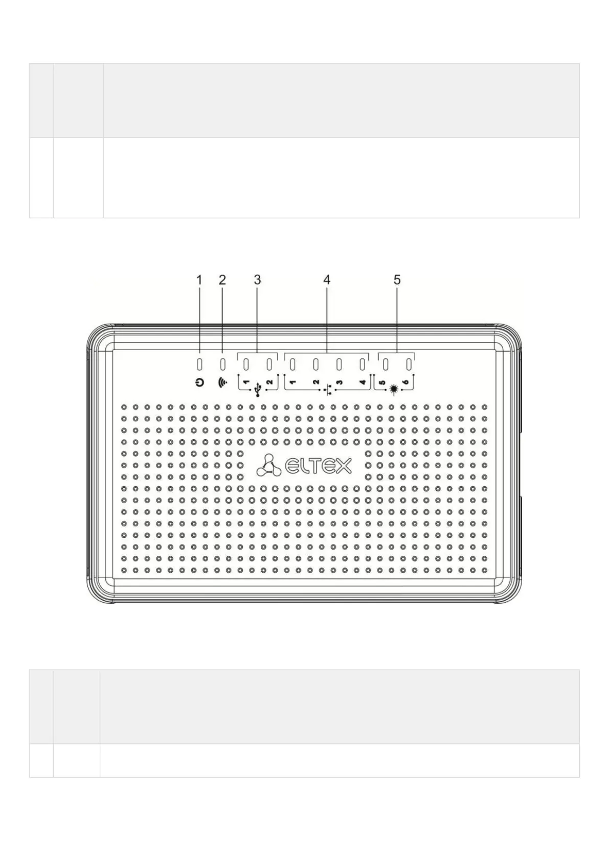
The top panel layout of ESR-10 is depicted in figure 42.
Figure 42 – ESR-10 top panel
Table 31 lists LEDs located on ESR-10 top panel.
Table 31 – Description of front panel LEDs
№ Top
panel
elemen
t
Description
1 Power Device power and operation status LED

 Loading...
