№ Front
panel
elemen
t
Description
1 ON/OFF Power on/off button
2 12V DC Connector for power adapter connection
3 Console RS-232 console port for local management of the device
4 USB1,
USB2
2 USB connectors for connecting external USB devices
5 [1 .. 4] 4 ports of Gigabit Ethernet – 10/100/1000BASE-T (RJ-45)
6 Optical
Ports
2 ports of Gigabit Ethernet-100/1000BASE-X (SFP)
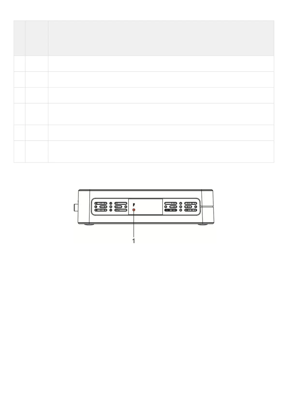
ESR-10 side panels
The side panel layout of ESR-10 is depicted in figure 41.
Figure 41 – ESR-10 side panel
Table 30 lists right panel controls of the router.

 Loading...
