Table 28 – Rear panel connectors description
№ Description
1 Earth bonding point of the device.
ESR-12V side panels
The side panel layout of ESR-12V is depicted in figures 38 and 39.
Figure 38 – ESR-12V left side panel
Figure 39 – ESR-12V right side panel
Side panels of the device have air vents for heat removal. Do not block air vents. This may cause the
components to overheat, which may result in device malfunction. For recommendations on device installation,
see section Installation and connection.
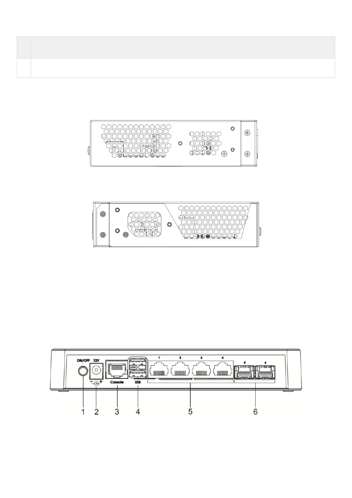
2.4.10 ESR-10 design
ESR-10 rear panel
The rear panel layout of the device is depicted in figure 40.
Figure 40 – ESR-10 rear panel
Table 29 lists connectors, LEDs and controls located on the rear panel of ESR-10.
Table 29 – Description of connectors, LEDs and controls located on ESR-10 rear panel

 Loading...
