2.4.3 ESR-1511, ESR-1510 design
ESR-1511 front panel
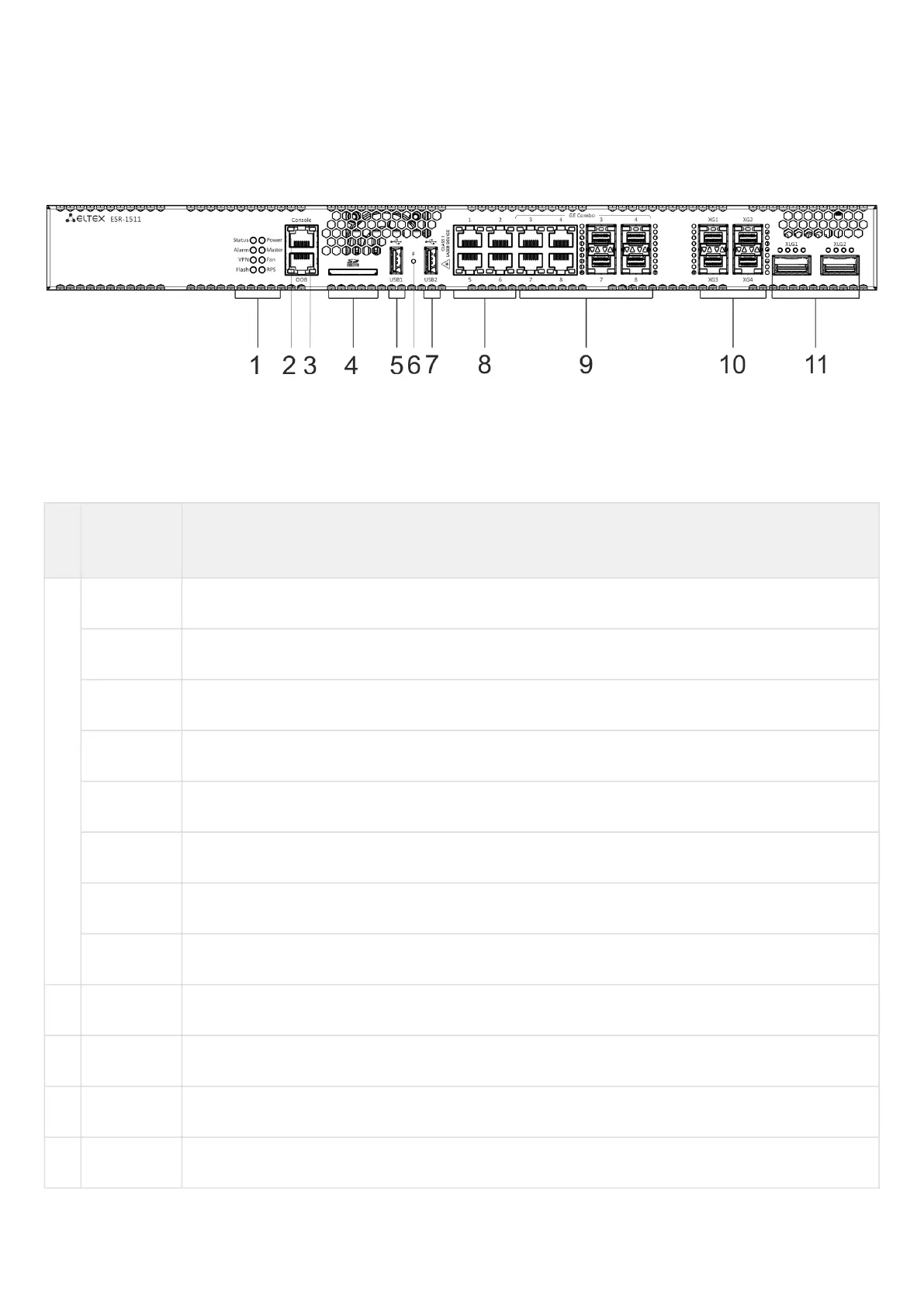
The front panel layout is depicted in figure 9.
Figure 9 – ESR-1511 front panel
Table 13 lists connectors, LEDs and controls located on the front panel of ESR-1511.
Table 13 – Description of connectors, LEDs and controls located on ESR-1511 front panel
№ Front panel
element
Description
1 Status Current device status LED.
Alarm Alarm LED.
VPN VPN gateway operation mode LED (is not supported in the current version).
Flash Activity of exchange with data storage – SD card or USB Flash.
Power Device power LED.
Master Failover mode operation LED (is not supported in the current version).
Fan Fan operation LED.
RPS Redundant power supply LED.
2 Console Console port RS-232 for local management of the device.
3 OOB Ethernet port for router management.
4 SD SD-card connector.
5 USB1 Port for USB device connection.

 Loading...
