•
•
№ Front panel
element
Description
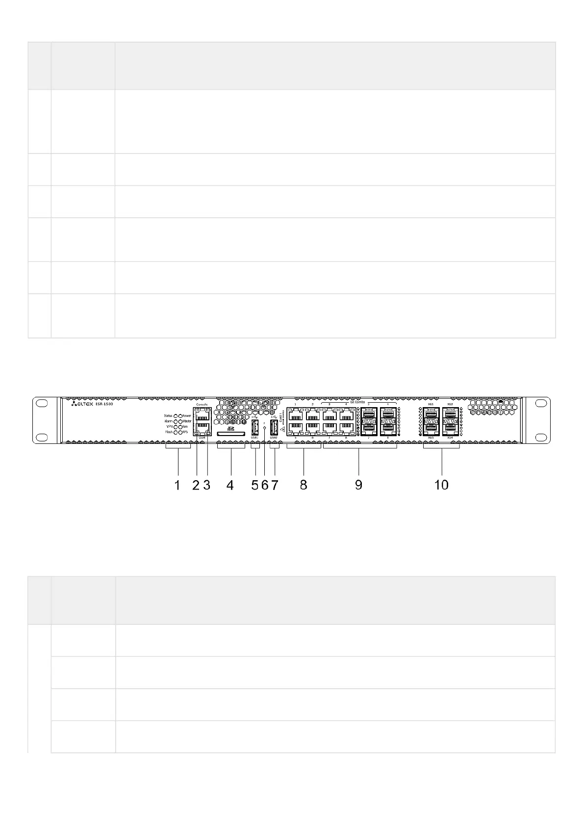
6 F Functional key that reboots the device and resets it to factory default configuration:
Pressing the key for less than 10 seconds reboots the device;
Pressing the key for more than 10 seconds resets the terminal to factory settings.
7 USB2 Port for USB device connection.
8 Ethernet 4 ports of Ethernet 10/100/1000BASE-T.
9 Combo
Ports [1 .. 4]
4 ports of Gigabit Ethernet 10/100/1000BASE-X (SFP).
10 XG1 – XG4 Slots for 10G SFP+/1G SFP transceivers.
11 XLG1 –
XLG2
Slots for 40G QSFP+ transceivers.
ESR-1500 front panel
The front panel layout is depicted in figure 10.
Figure 10 – ESR-1500 front panel
Table 14 lists connectors, LEDs and controls located on the front panel of ESR-1500.
Table 14 – Description of ESR-1500 connectors, LEDs and front panel controls
№ Front panel
element
Description
1 Status Current device status LED.
Alarm Alarm LED.
VPN VPN gateway operation mode LED (is not supported in the current version).
Flash Activity of exchange with data storage – SD card or USB Flash.

 Loading...
