2.4.4 ESR-1200, ESR-1000 design
ESR-1200 front panel
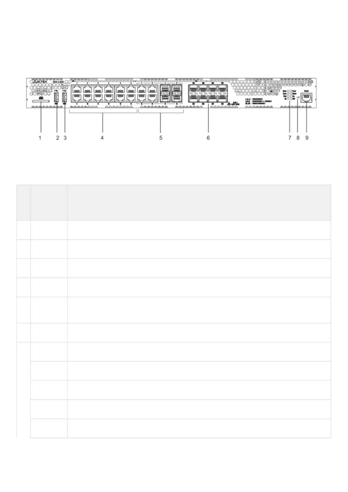
The front panel layout is depicted in 14.
Figure 14 – ESR-1200 front panel
Table 16 lists connectors, LEDs and controls located on the front panel of ESR-1200.
Table 16 – Description of connectors, LEDs and controls located on the front panel of ESR-1200
№ Front
panel
element
Description
1 SD SD-card connector.
2 USB1 Port for USB device connection.
3 USB2 Port for USB device connection.
4 [1 .. 12] 12 ports of Gigabit Ethernet 10/100/1000BASE-T (RJ-45).
5 Combo
Ports
4 ports of Gigabit Ethernet 10/100/1000BASE-X (SFP).
6 XG1 – XG8 Slots for installation of 10G SFP+/1G SFP transceivers.
7 Status Current device status LED.
Alarm Alarm LED.
HA НА operation mode LED.
Flash Activity indicator of exchange with data storages (SD-card or USB Flash).
Power Device power LED.

 Loading...
