EasyManuals Logo

ELTEX ESR Series User Manual

ELTEX ESR Series
575 pages
To Next Page IconTo Next Page
To Previous Page IconTo Previous Page
Page #41 background imageLoading...
Page #41 background image
ESR-Series. User manual
41
ESR-1511, ESR-1500 rear panel
The rear panel layout of ESR-1511 and ESR-1500 routers is depicted in figure 11.
Figure 11 – ESR-1511, ESR-1500 rear panel
Table 15 lists rear panel connectors of the router.
Table 15 – Rear panel connectors description
Description
1 Main power supply.
2 Earth bonding point of the device.
3 Hot-swappable removable ventilation modules.
4 Place for installation of a redundant power supply.
ESR-1511, ESR-1500 side panels
The side panel layout of ESR-1511, ESR-1500 is depicted in Figures 12 and 13.
Figure 12 – ESR-1511, ESR-1500 right side panel
Figure 13 – ESR-1511, ESR-1500 left side panel
Side panels of the device have air vents for heat removal. Do not block air vents. This may cause the
components to overheat, which may result in device malfunction. For recommendations on device installation,
see section Installation and connection.
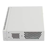
Table of Contents

Questions and Answers:

Question and Answer IconNeed help?

Do you have a question about the ELTEX ESR Series and is the answer not in the manual?

ELTEX ESR Series Specifications

General IconGeneral
ModelESR Series
CategoryNetwork Router
ManufacturerELTEX
ManagementWeb interface, CLI, SNMP
Operating Temperature0°C to 40°C
DimensionsVaries by model
WeightVaries by model
Routing ProtocolsOSPF, BGP
WAN InterfacesEthernet, SFP
LAN InterfacesEthernet, SFP
VPN SupportIPsec, L2TP, PPTP
FirewallStateful packet inspection, ACLs
Power over Ethernet (PoE)Available on some models
QoSTraffic prioritization

Related product manuals