2.4.6 ESR-21 design
The device has a metal housing available for 19” form-factor rack mount; housing size is 1U.
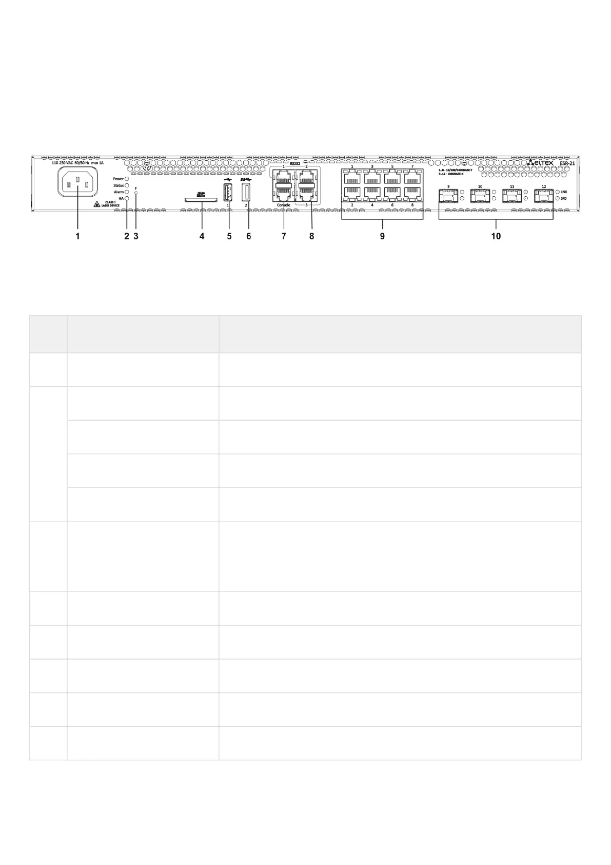
ESR-21 front panel
The front panel layout of ESR-21 is depicted in figure 24.
Figure 24 – ESR-21 front panel
Table 21 lists sizes, LEDs and controls located on ESR-21 front panel.
Table 21 – Description of connectors, LEDs and controls located on ESR-21 front panel
№ Front panel element Description
1 220V АC Power supply
2 Power Device power LED
Status Device status LED
Alarm Device alarm presence and level LED
HA HA operation mode LED (is not supported in the current version)
3 F Functional key that reboots the device and resets it to factory default
configuration: - pressing the key for less than 10 seconds reboots the device.
- pressing the key for more than 10 seconds resets the device to factory
default configuration.
4 SD SD-card connector
5 USB1 USB 2.0 connector for connecting external USB devices
6 USB2 USB 3.0 connector for connecting external USB devices
7 Console Console port for local management of the device
8 RS-232 3 serial ports

 Loading...
