Table 10 – Rear panel connectors description
№ Description
1 Earth bonding point of the device.
2 Hot-swappable removable ventilation modules.
3 Main power supply.
4 Place for installation of a redundant power supply.
ESR-1700 side panels
The side panel layout of ESR-1700 is depicted in figures 3 and 4.
Figure 3 – ESR-1700 right side panel
Figure 4 – ESR-1700 left side panel
Side panels of the device have air vents for heat removal. Do not block air vents. This may cause the
components to overheat, which may result in device malfunction. For recommendations on device installation,
see section Installation and connection.
2.4.2 ESR-3100 design
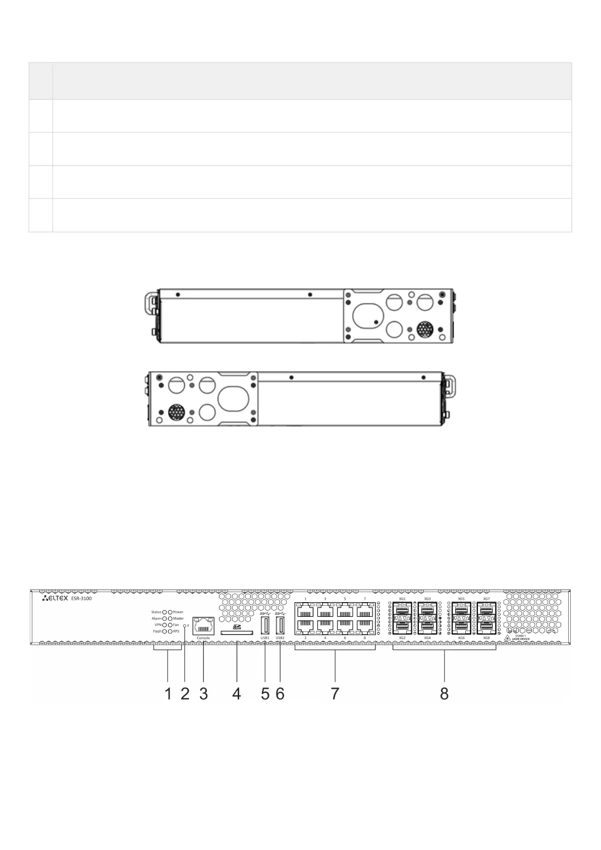
ESR-3100 front panel
The front panel layout is depicted in 5.
Figure 5 – ESR-3100 front panel
Table 11 lists connectors, LEDs and controls located on the front panel of ESR-3100.

 Loading...
