ESR-12V(F) light indication
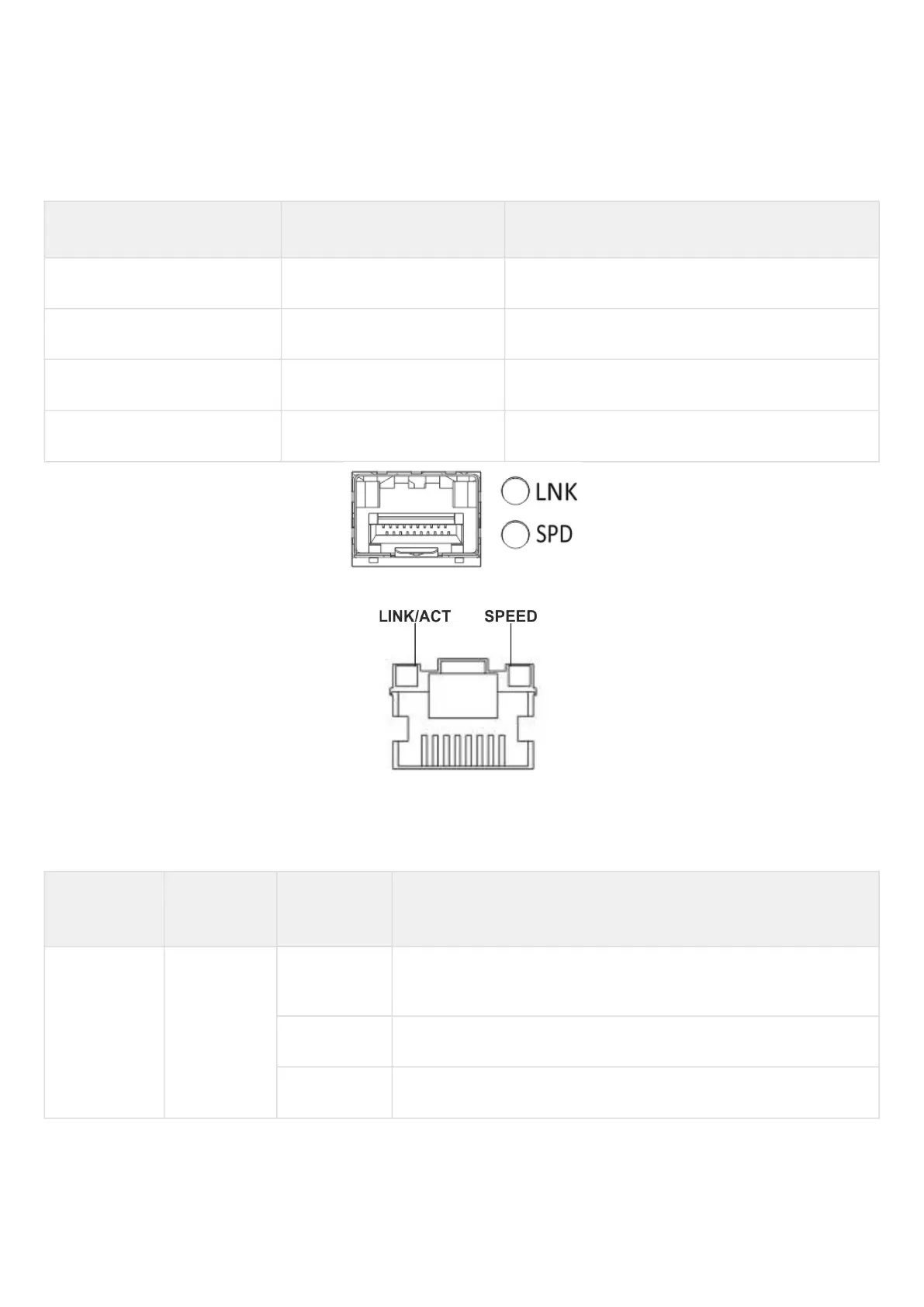
Gigabit Ethernet copper interface statuses are represented by two LEDs – green LINK/ACT LED and amber
SPEED LED.
Table 39 – Light indication of copper and SFP interface status
SPEED indicator is lit LINK/ACT indicator is lit Ethernet interface state
Off Off Port is disabled or connection is not established
Off Solid on 10Mbps or 100Mbps connection is established
Solid on Solid on 1000Mbps connection is established
X Flashes Data transfer is in progress
Figure 48 – Location of SFP connector indicators (only for ESR-12VF, ESR-14VF)
Figure 49 – Location of RJ-45 connector indicators
The following table lists description of system indicator statuses and meanings.
Table 40 – Status of system indicators
Indicator
name
Indicator
function
LED State Device State
Power Device power
LED.
Green Device power is OK. Main power supply, if installed, is operational.
The main software is uploaded.
Red The main software is not uploaded.
Off Device internal power supply failure.

 Loading...
