EPSON AcuLaser C1100 Revision B
DISASSEMBLY AND ASSEMBLY DUPLEX 415
4.12.4 COVER-INV
REMOVAL
1. Remove DUPLEX ASSY. (p.412)
2. Remove COVER-R DUP. (p.413)
3. Remove COVER-L DUP. (p.414)
4. Remove LINK LATCH and LINK-BUTTON. (p.416)
5. Open COVER UP-DUP TRANS, and remove INVERTER ASSY DUP. Note that
COVER LOW-DUP TRANS and COVER UP-DUP TRANS need not be
removed. (p.417)
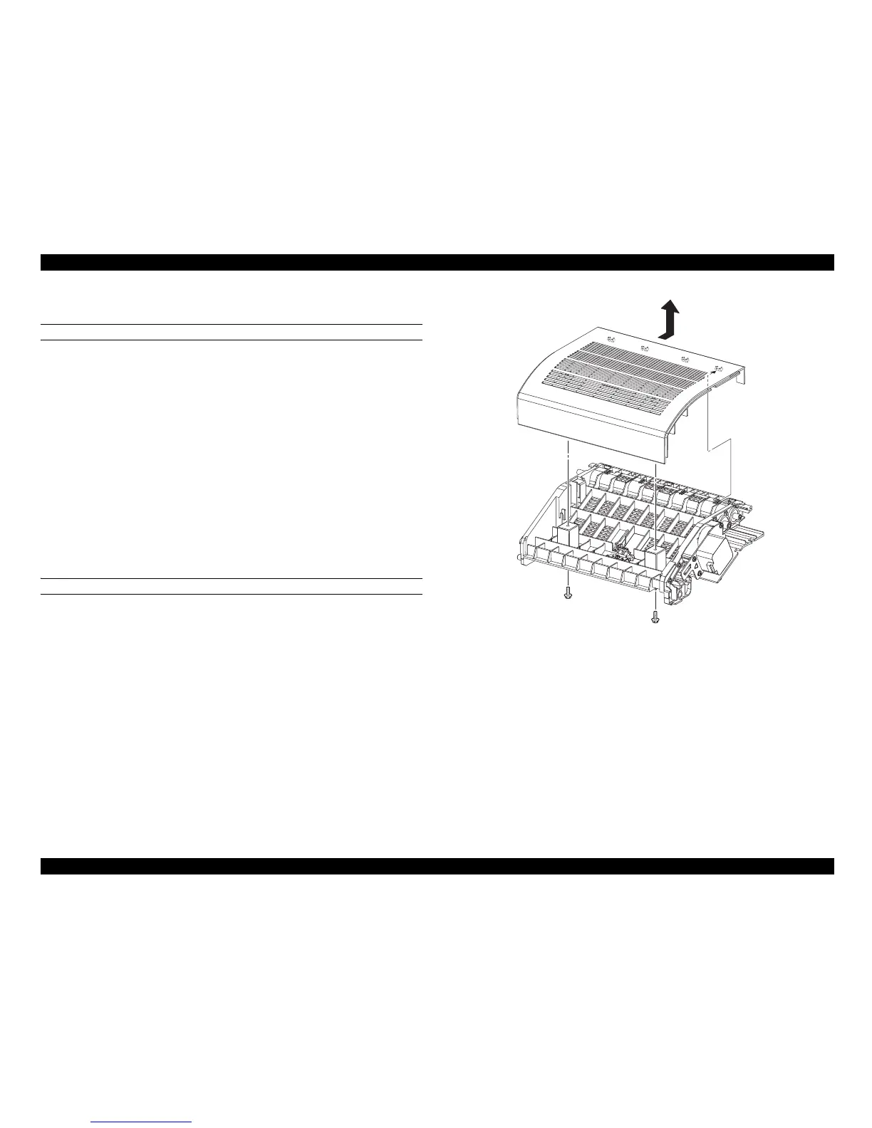
6. Remove the 2 screws (silver, with flange, tapping, 10mm) fastening COVER-INV
to INVERTER ASSY DUP.
7. Slide COVER-INV to the front side, unhook the 4 holes on the rear of COVER-
INV from the hooks on INVERTER ASSY DUP, and remove COVER-INV.
REINSTALLATION
1. Match the 4 holes on the rear of COVER-INV with the hooks on INVERTER
ASSY DUP, and attach COVER-INV.
2. Attach COVER-INV to INVERTER ASSY DUP with the 2 screws (silver, with
flange, tapping, 10 mm).
3. Attach INVERTER ASSY DUP. (p.417)
4. Attach LINK LATCH and LINK-BUTTON. (p.416)
5. Attach COVER-L DUP. (p.414)
6. Attach COVER-R DUP. (p.413)
7. Attach DUPLEX ASSY. (p.412)
Figure 4-118. Removal of COVER-INV
Leg_Sec03_119FA
7)-2
7)-1
6)
6)