EPSON AcuLaser C1100 Revision B
DISASSEMBLY AND ASSEMBLY 500 PAPER CASSETTE & 500 PAPER FEEDER 458
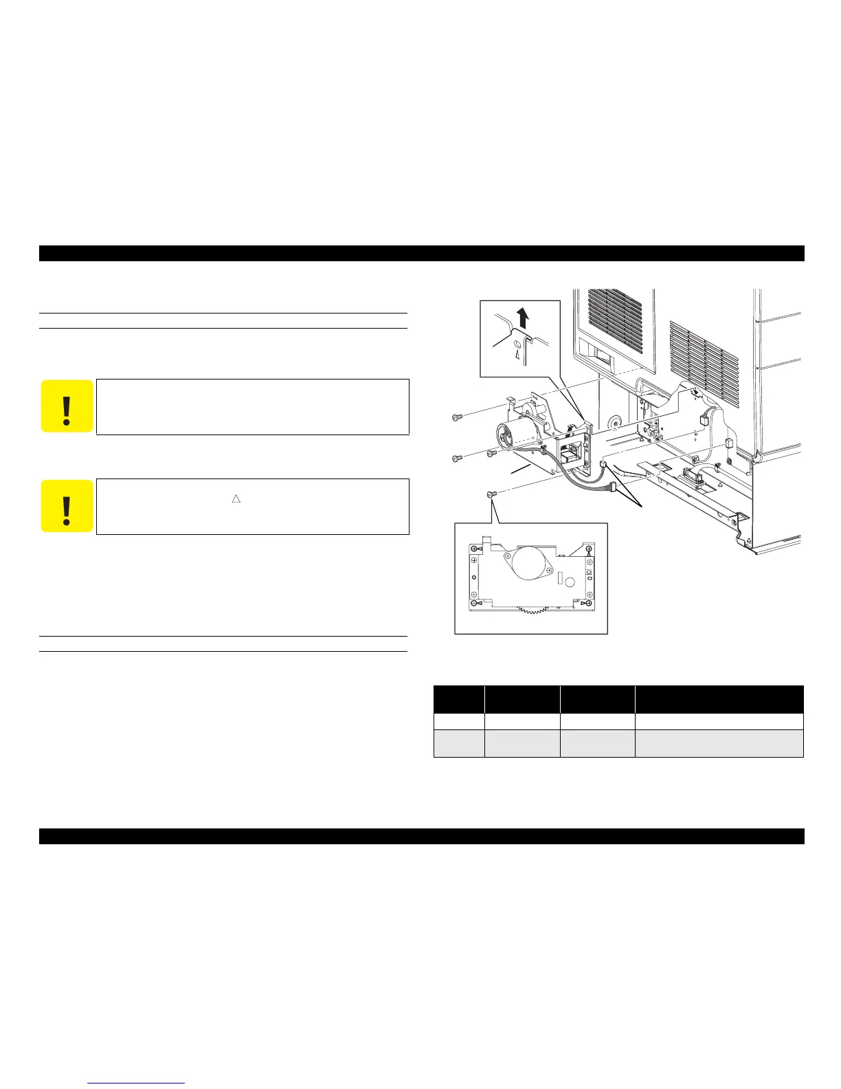
4.13.12 DRIVE ASSY FEED
REMOVAL
1. Remove COVER LEFT 500. (p.453)
2. Remove CLUTCH ASSY FEED. (p.461)
3. Disconnect connector (P/J446) from PWBA MOT and connector (P/J610) from
SOLENOID FEED.
4. Remove the 4 screws (silver, 6 mm) fastening DRIVE ASSY FEED to 500
PAPER FEEDER ASSY.
5. Remove the protrusion on the top right of DRIVE ASSY FEED from 500 PAPER
FEEDER ASSY, and remove DRIVE ASSY FEED.
REINSTALLATION
1. Hook the protrusion on the top right of DRIVE ASSY FEED onto the notch on
500 PAPER FEEDER ASSY, and match the hole on DRIVE ASSY FEED with
the boss on 500 PAPER FEEDER ASSY to attach.
2. Fasten DRIVE ASSY FEED to 500 PAPER FEEDER ASSY with the 4 screws
(silver, 6 mm).
3. Connect connector (P/J446) to PWBA MOT and connector (P/J610) to
SOLENOID FEED.
4. Attach CLUTCH ASSY FEED. (p.461)
5. Attach COVER LEFT 500. (p.453)
Figure 4-158. Removal of DRIVE ASSY FEED
C A U T I O N
When performing the following work, leave the intermediate
connector of the connector (P/J610) on SOLENOID FEED on the
harness side.
C A U T I O N
The screws to be removed in the following work are those fastening
the four corners (marked by
) on DRIVE ASSY FEED. Other
screws must not be removed.
Table 4-14. Symptoms when the connector is loose
Connector
No.
Panel Indication Symptom
Error Caused by Connector
Disconnection
P/J446 Jam LC, G FEEDER Jam ---
P/J610 Paper Out LC1
Printing is not
possible.
No paper in Paper Cassette
Leg_Sec03_023EA
CAUTION
3)
4)
5)-2
4)
4)
4)
5)-1