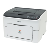
EPSON AcuLaser C1100 Revision B
APPENDIX Wiring Connection Diagram between Parts 529
8. 2ND BTR
Figure 7-15. 2nd BTR Connection and Wiring Diagram
Name of signal line Remarks
FUSER IN SENSED (L)+5VDC
2nd BTR paper detection signal generated by
Sensor Photo (Fuser In Sensor)
RETRACT SENSED (H)+5VDC
2nd BTR retract detection signal generated by
Sensor Photo (2nd BTR Retract Sensor)
ADC SOL RELEASE ON (L)+24VDC Sensor ADC internal Solenoid ON/OFF signal
ADC SOL NIP ON (L)+24VDC Sensor ADC internal Solenoid ON/OFF signal
ADC LED COLOR ON (L)+5VDC
Lighting signal of LED for detection of Sensor
ADC internal color toner patch
ADC LED BLACK ON (L)+5VDC
Lighting signal of LED for detection of Sensor
ADC internal black toner patch
ADC SENSOR
Toner patch density data (analog value)
measured by sensor
RETRACT MOT ON (H)+3.3VDC
RETRACT MOT PWM
2nd BTR Retract Motor control signal
PWBA MCU
PL12.2.1
4
5
6
PULL UP +5VDC
Interlock
+24VDC
7
8
SG
RETRACT SENSED (H) +5VDC
SG
COVER OPENED (H) +3.3VDC
P/J112
3
2
1
SENSOR
2BTR
RETRACT
PL6.1.22
SENSOR ASSY ADC
PL6.1.20
MOT ASSY MICRO
PL11.1.7
P/J422
1
2
3
4
5
6
+5VDC
1
P/J113
2
SWITCH
2BTR COVER
PL6.1.18
7
P/J431
8
ADC SOL RELEASE ON (L) +24VDC
I/L +24VDC
6
5
4
3
2
1
ADC SOL NIP ON (L ) +24VDC
SG
ADC LED COLOR ON (L) +5VDC
ADC LED BLACK ON (L) +5VDC
ADC SENSOR
+5VDC
7
8
P/J403
1
2
3
13
2
3
2
1
P/J600
RETRACT MOT ON (H) +3.3VDC
I/L +24VDC
1
P/J621
2
21
P/J418
1
2
3
SG
FUSER IN SENSED (L)+5VDC
+5VDC
SENSOR
FUSER IN
PL6.1.3
2
1
1
P/J620
3
22
31
+5VDC
SG
Interlock
+24VDC
P/J111
3
+5VDC
Leg_Sec007_009FB
M

 Loading...


