EPSON AcuLaser M2000D/M2000DN/M2010D/M2010DN Revision B
APPENDIX Connection Summary 161
Confidential
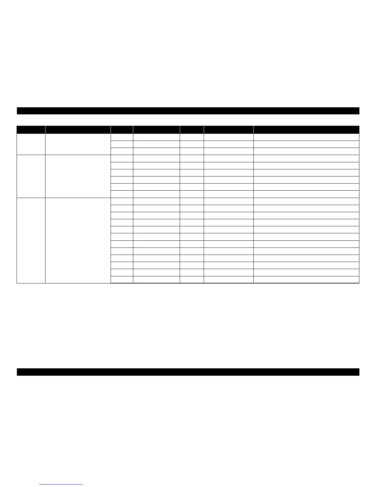
YC817 Duplex solenoid 1 DUDR1 O DC0V/24V Duplex solenoid (activate): On/Off
2 COMMON O DC24V DC24V power source
3 DUDR2 O DC0V/24V Duplex solenoid (return): On/Off
YC818 The first optional cassette unit 1 +24V3 O DC24V DC24V power source
2 PGND - -Ground
3 PFSI I DC0V/3.3V (pulse) Serial communication data input signal
4 PFSO O DC0V/3.3V (pulse) Serial communication data output signal
5 PFSEL O DC0V/3.3V Paper feeder selection signal
6 +3.3V1 O DC3.3V DC3.3V power source
YC819 Laser scanner unit 1 +24V3 O DC24V DC24V power source
2 PGND - -Ground
3 PLGDRN O DC0V/3.3V Polygon motor: On/Off
4 PLGRDY I DC0V/3.3V Polygon motor ready signal
5 PLGCLK O DC0V/3.3V (pulse) Polygon motor clock signal
6 PDN I DC0V/3.3V (pulse) Horizontal synchronizing signal
7 SGND - -Ground
8 VDON O DC0V/3.3V (pulse) Video data signal (+)
9 VDOP O DC0V/3.3V (pulse) Video data signal (-)
10 OUTPEN O DC0V/3.3V Laser output enable signal
11 SAMPLEN O DC0V/3.3V Sample/hold timing switching signal
12 +3.3V1 O DC3.3V DC3.3V power source
Connector No. Destination Pin No. Signal Name I/O Measured Voltage Function