AcuLaser M2000D/M2000DN/M2010D/M2010DN Revision B
OPERATING PRINCIPLES Technical Explanation of Print Process 22
Confidential
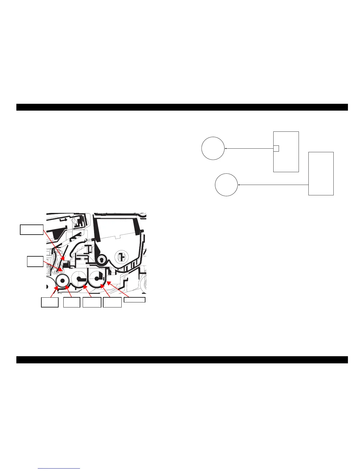
2.2.3 Development
The latent image constituted on the drum is developed into a visible image. The
developing roller contains a 3-pole (S-NS) magnet roller and an aluminum cylinder
rotating around the magnet roller. Toner attracts to the magnet sleeve since it is
powdery ink made of black resin bound to iron particles. Developing blade,
magnetized by magnet, is positioned approximately 0.3 mm above the magnet sleeve to
constitute a smooth layer of toner in accordance with the magnet sleeve revolution.
The developing roller is applied with the AC-weighted, positive DC power source.
Toner on the magnet sleeve is given a positive charge. The positively charged toner is
then attracted to the areas of the drum which was exposed to the laser light. (The gap
between the drum and the magnet sleeve is approximately 0.32 mm.) The non-exposed
areas of the drum repel the positively charged toner as these areas maintain the positive
charge.The developing roller is also AC-biased to ensure contrast in yielding by
compensating the toner’s attraction and repelling action during development.
Figure 2-10. Development section
Figure 2-11. Developing section block diagram
Blade
magnet
Magnet
sleeve
Magnet
roller
DLP
screw A
DLP
screw B
DLP case
Developing
blade
DLPDRN
Developing
clutch
YC808-6
B
Developing
roller
Magnet roller
Magnet sleeve
Developing bias output
HVPS
Main Board Assy.