Foundry Switch and Router Installation and Configuration Guide
6 - 12 December 2000
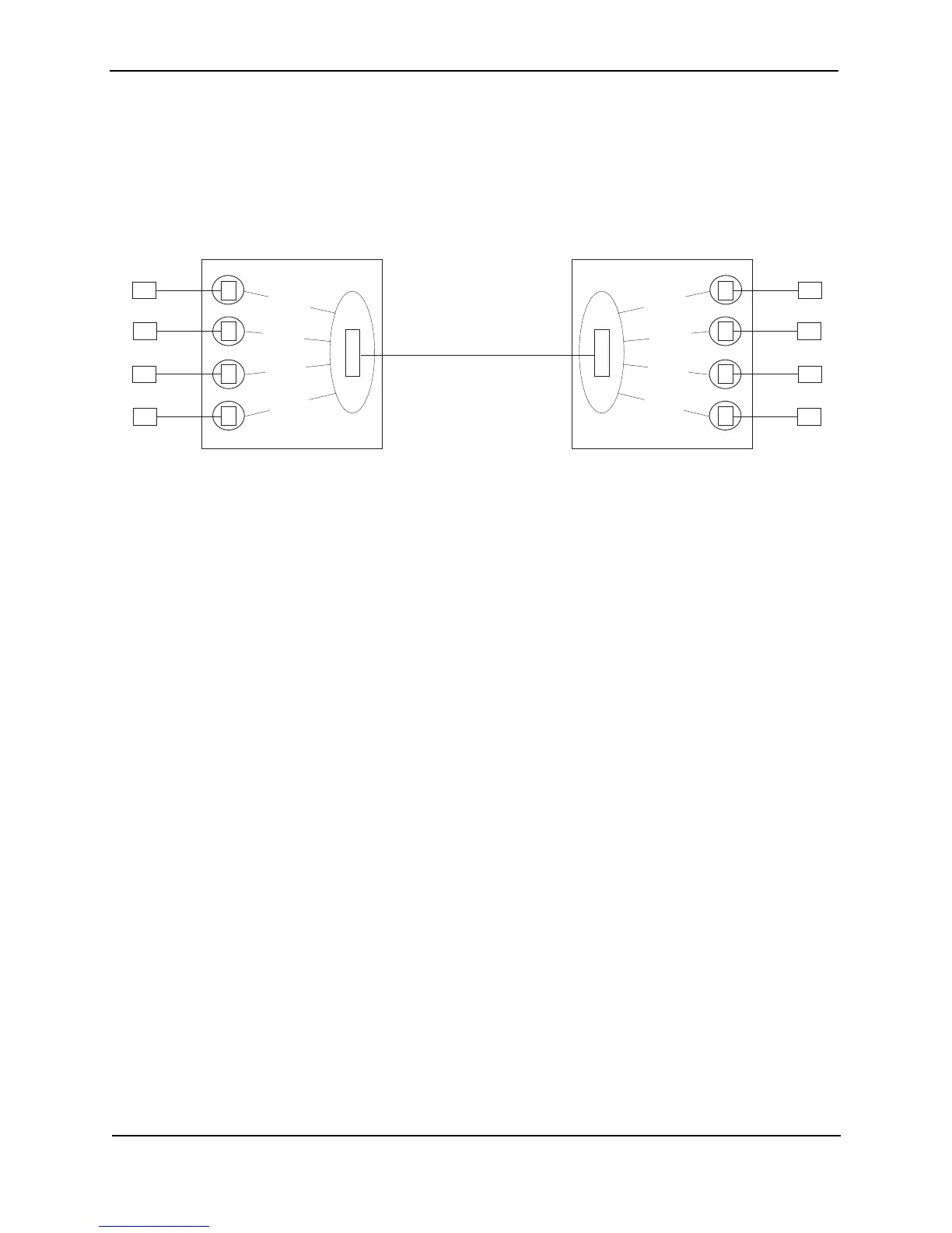
Figure 6.2 shows an example of a Layer 2 switching configuration using Layer 2 POS.
Figure 6.2 Basic POS Layer 2 switching configuration
This configuration shows four IP sub-nets. Each sub-net has members on both sides of the POS link. For
example, client C1 in the 192.168.1.x sub-net can communicate at Layer 2 with server S1 in the same sub-net,
even though the two devices are on different sides of the POS link.
S2
P
O
S
E
E
E
E
S3
S4
VLAN 40
S1
VLAN 10
VLAN 20
VLAN 30
C2
P
O
S
E
E
E
C3
C4
VLAN 40
C1
VLAN 10
VLAN 20
VLAN 30
Foundry switch B
E
192.168.2.20192.168.2.10
192.168.3.20
192.168.3.10
192.168.4.20
192.168.4.10
192.168.1.20
192.168.1.10
Ethernet over POS
Each client and its server on the other
Foundry device are in the same sub-net.
Traffic between each client and its server
is bridged over a PPP link on the SONET
link on the Layer 2 POS ports.
Each client and its server are in their
own port-based VLAN. The POS
ports are configured in all the client
or server VLANs.
Foundry switch A