Configuring Virtual LANs (VLANs)
December 2000 25 - 17
EXAMPLE:
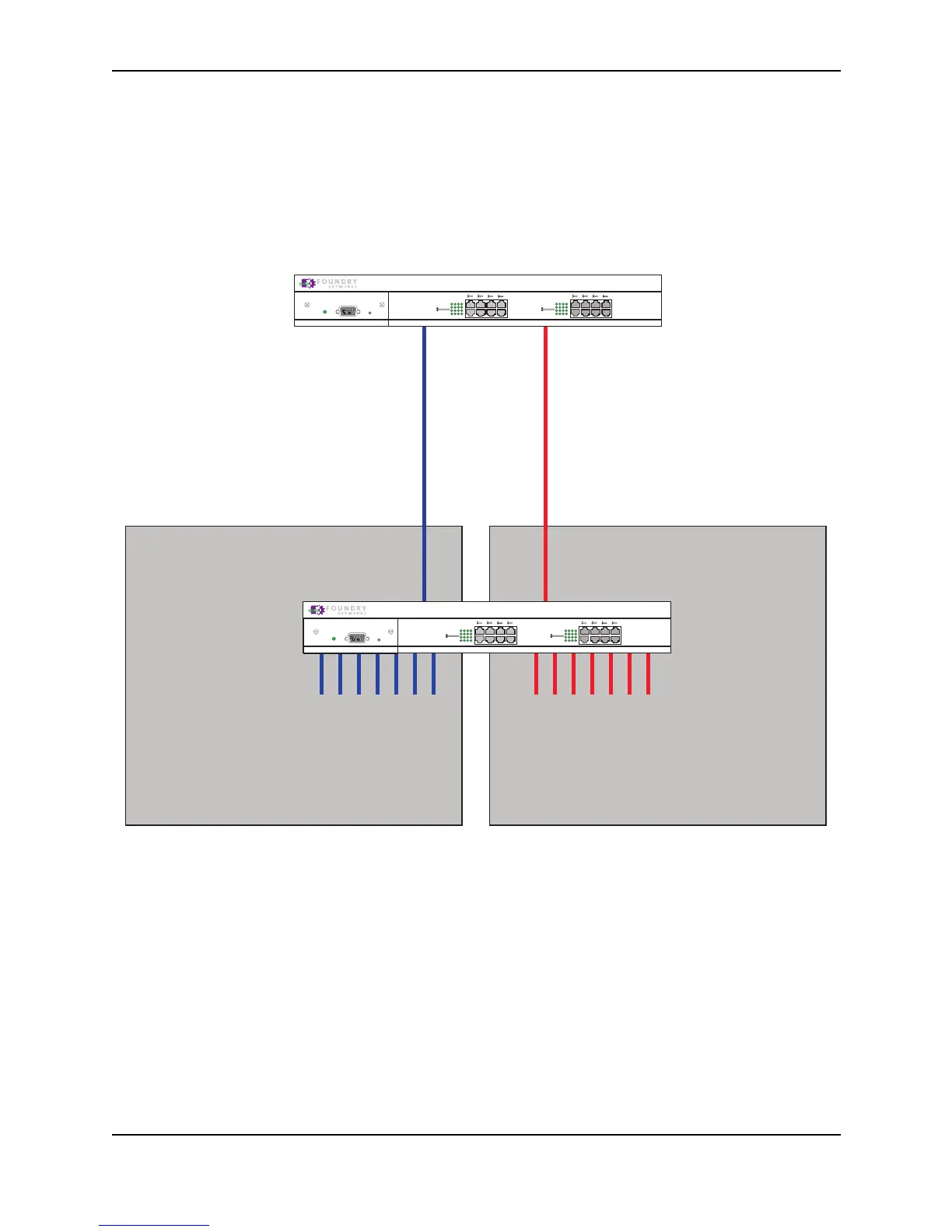
Figure 25.11 shows a simple port-based VLAN configuration using a single Foundry Layer 2 Switch. All ports
within each VLAN are untagged. One untagged port within each VLAN is used to connect the Layer 2 Switch to a
Layer 3 Switch (in this example, a NetIron) for Layer 3 connectivity between the two port-based VLANs.
Figure 25.11 Port-based VLANs 222 and 333
To create the two port-based VLANs shown in Figure 25.11, use the following method.
USING THE CLI
FastIron(config)# vlan 222 by port
FastIron(config-vlan-222)# untag e1 to 8
FastIron(config-vlan-222)# vlan 333 by port
FastIron(config-vlan-333)# untag e9 to 16
Syntax: vlan <vlan-id> by port
Syntax: untagged ethernet <portnum> [to <portnum> | ethernet <portnum>]
VLAN 222
Ports 1 - 8
VLAN 333
Ports 9 - 16
NetIron Router
1
2
3
4
5
6
7
8
FDX
Link/Act
FDX
Link/Act
9
10
11
12
13
14
15
16
FDX
Link/Act
FDX
Link/Act
Power
Console
Port 1 Port 9
FastIron
NetIron Router
FastIron Workgroup
1
2
3
4
5
6
7
8
FDX
Link/Act
FDX
Link/Act
9
10
11
12
13
14
15
16
FDX
Link/Act
FDX
Link/Act
Power
Console
Ports 2 - 8
IP Subnet 1
IPX Network 1
AppletalkCable-Range 100
AppletalkZonePrepress
Ports 9 - 16
IP Subnet 2
IPX Network 2
AppletalkCable-Range 200
AppletalkZone CTP
interface e 2
IP Subnet 2
IPX Network 2
AppletalkCable-Range 200
AppletalkZone CTP
interface e 1
IPX Network 1
AppletalkCable-Range 100
AppletalkZonePrepress
IP Subnet 1