Foundry Switch and Router Installation and Configuration Guide
20 - 14 December 2000
Configuration Examples
This section shows two complete configuration examples for NAT. The examples are based on different network
topologies.
• NAT clients connected to the Layer 3 Switch by a Layer 2 Switch.
• NAT clients connected directly to Layer 3 Switch ports.
NOTE: You also can enable the feature on the primary port of a trunk group, in which case the feature applies to
all the ports in the trunk group. These examples do not show this configuration.
Private NAT Clients Connected to the Layer 3 Switch by a Layer 2 Switch
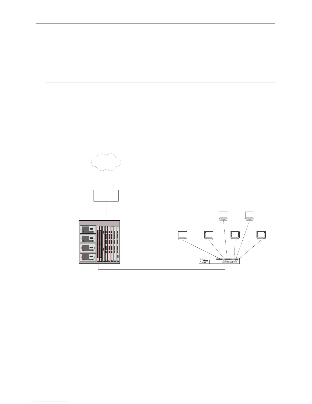
Figure 20.2 shows an example of a NAT configuration in which the clients in the private network are attached to
the Layer 3 Switch through a Layer 2 Switch.
Figure 20.2 NAT clients connected the Layer 3 Switch by a Layer 2 Switch
Here are the CLI commands for implementing the NAT configuration shown in Figure 20.3. These commands
configure the following:
• An IP address and default gateway on the Layer 2 Switch
• An Access Control List (ACL) for the range of private addresses in the private network on virtual interface 10
• A Pool of public (Internet) address to use for translation of the private addresses
• An association of the ACL for the private addresses with the pool for translation
• A default route that has the Internet access router as the route’s next-hop gateway
The commands also enable inside NAT and outside NAT on the ports connected to the private network’s Layer 2
Switch and to the Internet access router, and save the configuration changes to the startup-config file.
Internet
10.10.10.7
The switching router performs
NAT for traffic between the
outside NAT interface and the
inside NAT interface.
NAT Pool = 63.251.295.47/26 - 63.251.295.48/26
Internet
access router
Power
Link
Activity
Link
Activity
Console
10.10.10.610.10.10.5
10.10.10.410.10.10.3
10.10.10.2
10.10.10.49/26
Outside NAT interface
Port 4/1
63.251.295.46/26
Inside NAT interface
Port 1/24
10.10.10.50/26
63.251.295.1/26