Configuring IP
December 2000 15 - 3
The number of IP addresses you can configure on an individual interface depends on the Layer 3 Switch model.
To display the maximum number of IP addresses and other system parameters you can configure on a Layer 3
Switch, see “Displaying and Modifying System Parameter Default Settings” on page 10-70.
You can use any of the IP addresses you configure on the Layer 3 Switch for Telnet, Web management, or SNMP
access.
Layer 2 Switches
You can configure an IP address on a Foundry Layer 2 Switch for management access to the Layer 2 Switch. An
IP address is required for Telnet access, Web management access, and SNMP access.
You also can specify the default gateway for forwarding traffic to other sub-nets.
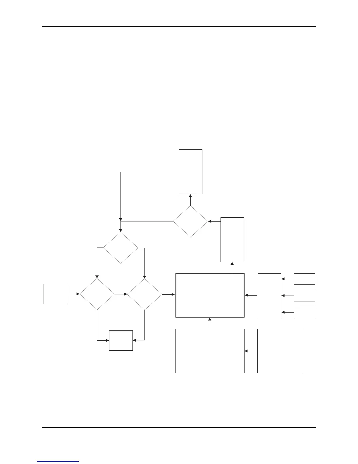
IP Packet Flow Through a Layer 3 Switch
Figure 15.1 shows how an IP packet moves through a Foundry Layer 3 Switch.
Figure 15.1 IP Packet flow through a Foundry Layer 3 Switch
BGP4
N
Y
Mult.
Equal-
cost
Paths
Outgoing
Port
Load
Balancing
Algorithm
OSPF
RIP
Static ARP
Ta bl e
Lowest
Admin.
Distance
Y
N
Incoming
Port
N
Y
Fwding
Cache
Session
Table
PBR
or
IP acc
policy
Lowest
Metric
N
Y
IP Route
Table
ARP
Cache