Foundry Switch and Router Installation and Configuration Guide
6 - 16 December 2000
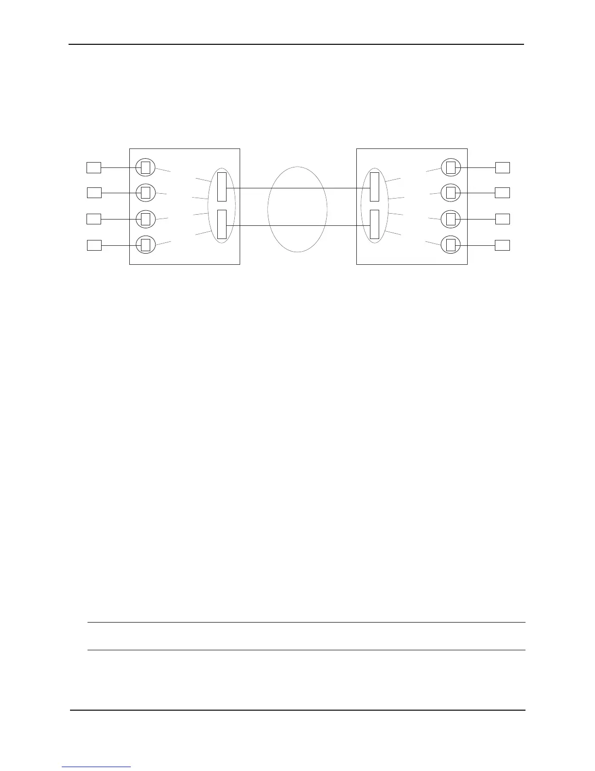
Figure 6.6 POS Layer 2 port redundancy using a trunk group
This example shows a trunk group configured on a POS module in each chassis. In each module, both POS ports
are configured together as a single link. The links load share and also provide redundancy. If a link in a trunk
group becomes unavailable, the connection is maintained by the other link.
You can use STP with trunk group links. STP regards a trunk group as a single link and thus either forwards or
blocks traffic on all the ports within the trunk group.
Configuration Procedures
To configure a Foundry device for POS Layer 2 switching:
• Change POS interface parameters, if you need to change a parameter from its default value.
• Configure each host sub-net in a separate port-based VLAN.
• Add the POS port as a tagged port to all the host port-based VLANs.
• Optionally, configure redundancy by configuring a second POS port as above, then doing one of the
following:
• Configuring Spanning Tree Protocol (STP) parameters on the ports.
• Adding the POS ports to a trunk group. If you add the ports to a trunk group, the ports load balance
traffic in addition to providing link redundancy.
Configuring a POS Port for Layer 2 Switching
POS ports are configured for Layer 3 IP routing by default. To configure a POS port for Layer 2 switching, you
must add the port as a tagged port to a port-based VLAN.
NOTE: Layer 2 POS ports must be tagged. You cannot add a POS port to a port-based VLAN without tagging
the port.
A POS port is by default a routing-only port. That is, it is by default not a member of the default Layer 2 broadcast
domain (VLAN 1). You can convert a POS port to a Layer-2 switching-only port by adding it to one or more VLANs
as a tagged port. Only traffic from ports belonging to the same VLANs as the tagged POS port are forwarded.
P
O
S
S2
P
O
S
E
E
E
E
S3
S4
VLAN 40
S1
VLAN 10
VLAN 20
VLAN 30
P
O
S
C2
P
O
S
E
E
Fwd
E
C3
C4
VLAN 40
C1
VLAN 10
VLAN 20
VLAN 30
The POS ports are configured
in a trunk group. The links load
share traffic and also provide
redundancy in case a link
becomes unavailable.
Fwd
Fwd
Fwd
E
192.168.2.20192.168.2.10
192.168.3.20
192.168.3.10
192.168.4.20
192.168.4.10
192.168.1.20
192.168.1.10
Ethernet over POS
Each client and its server on the other
Foundry device are in the same sub-net.
Traffic between each client and its server
is bridged over a PPP link built on the POS
link on the Layer 2 POS ports.
Each client and its server are in their
own port-based VLAN. The VLAN ports
are tagged. The POS ports are configured
in all the client or server VLANs.
Foundry switch B
Foundry switch A