Configuring IP
December 2000 15 - 57
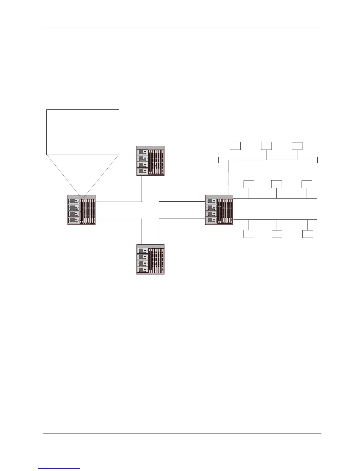
Figure 15.7 shows an example of IP load sharing cache entries for network-based IP load sharing. The network in
this example is the same as the network in Figure 15.5 and Figure 15.6. Notice that the cache contains one entry
for each destination network, instead of a separate entry for each destination host. Based on the cache entries,
traffic for all hosts (H1, H2, and H3) on network N1 uses the path through R2.
Figure 15.7 Network-based IP load sharing – basic example
Notice that network-based load sharing does not use a simple round-robin method. The path rotation starts with
path 2, then proceeds in ascending numerical order through the remaining paths and ends with path 1. In Figure
15.7, the first cache entry uses path 2 instead of path 1. The algorithm evenly distributes the load among the
available paths, but starts with the second path instead of the first path.
For optimal results, set the maximum number of paths to a value at least as high as the maximum number of
equal-cost paths your network typically contains. For example, if the Layer 3 Switch you are configuring for IP
load sharing has six next-hop routers, set the maximum paths value to six. See “Changing the Maximum Number
of Load Sharing Paths” on page 15-62.
NOTE: If the setting for the maximum number of paths is lower than the actual number of equal-cost paths, the
software does not use all the paths for load sharing.
The network-based IP load sharing mechanism selects a path based on the following calculation, which involves
the maximum number of paths allowed on the Layer 3 Switch and the number of equal-cost paths available to the
destination network.
M modulo P + 1 = S
where:
H6
192.168.2.155
H5
192.168.2.193
H4
192.168.2.175
H9
192.168.3.111
H3
192.168.1.218
H2
192.168.1.170
H1
192.168.7.1
H8H7
192.168.3.159192.168.3.209
IP Forwarding Cache
Network-Based Load Sharing
Destination Network
192.168.1.0 (N1)
192.168.2.0 (N2)
192.168.3.0 (N3)
Next-Hop
192.168.6.2 (R2)
192.168.6.2 (R3)
192.168.5.1 (R2)
192.168.1.1 (N1)
192.168.2.1 (N2)
192.168.3.1 (N3)
192.168.7.2
192.168.4.1
192.168.6.2
192.168.5.2
192.168.4.2192.168.5.1
192.168.1.234
192.168.6.1
R4
R3
R2
R1
R1 is configured with four IP load
sharing paths, and has two paths
to networks N1 - N3, attached to R4.
The cache entries in this example
are based on the assumption that
R1 receives traffic for hosts in N1 - N3
in that order.
Once a packet for a host on N1 is received,
the cache entry applies to all hosts on N1.
The same applies for N2 and N3.
 Loading...
