Network Address Translation
December 2000 20 - 17
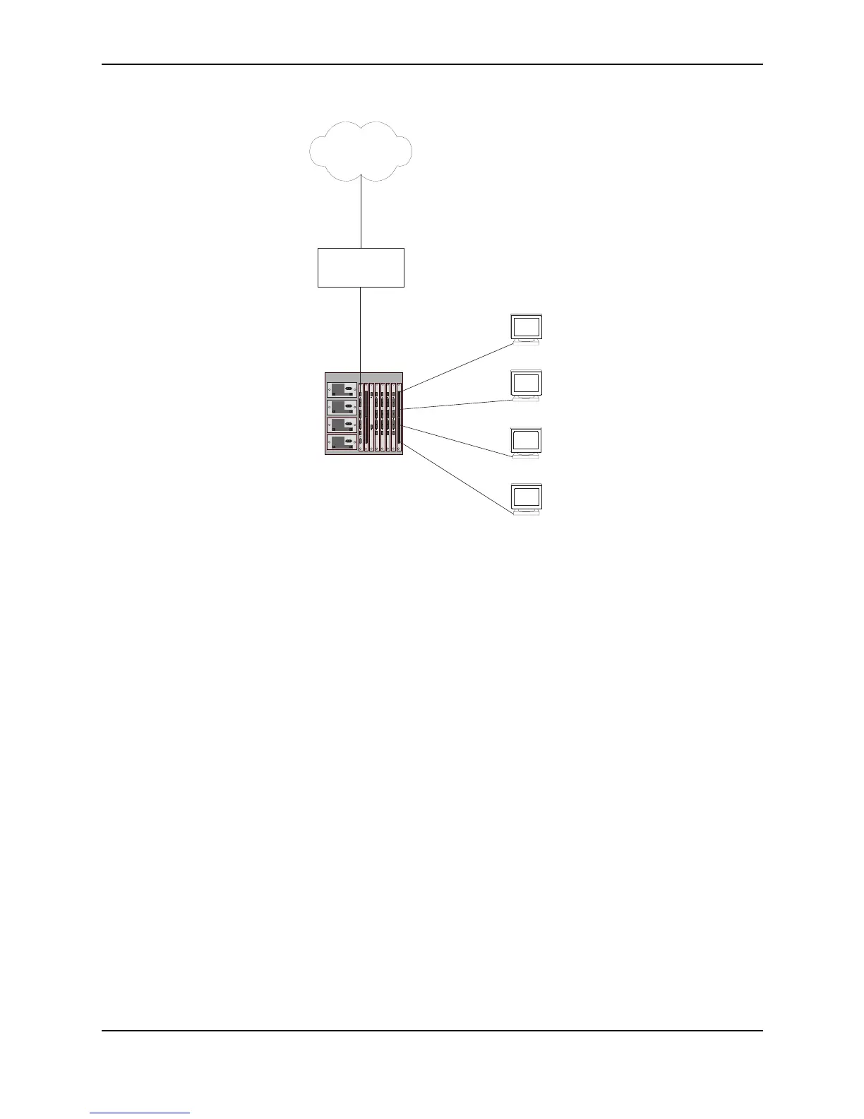
Figure 20.3 NAT clients connected directly to the Layer 3 Switch
Here are the CLI commands for implementing the NAT configuration shown in Figure 20.3. These commands
configure the following:
• Port-based VLAN 2 and virtual interface 10 for the inside NAT interface
• Port-based VLAN 3 and virtual interface 15 for the outside NAT interface
• An Access Control List (ACL) for the range of private address in the private network on virtual interface 10
• A Pool of public (Internet) address to use for translation of the private addresses
• An association of the ACL for the private addresses with the pool for translation
• A default route that has the Internet access router as the route’s next-hop gateway
The commands also enable inside NAT and outside NAT on the virtual interfaces and save the configuration
changes to the startup-config file. All the commands are entered on the Layer 3 Switch.
The following commands access the configuration level of the CLI, then configure port-based VLAN 2 and add
virtual interface 10 to the VLAN.
BigIron> en
BigIron# configure terminal
BigIron(config)# vlan 2 by port
BigIron(config-vlan-2)# untagged ethernet 8/1 to 8/24
BigIron(config-vlan-2)# router-interface ve 10
BigIron(config-vlan-2)# exit
These commands add ports 8/1 through 8/24 as untagged ports to port-based VLAN 2. Generally, unless a port is
a member of more than one port-based VLAN, you do not need to tag the port. The router-interface 10
command adds virtual interface 10. At this point the virtual interface does not have an IP address associated with
it.
The following commands add port-based VLAN 3 and add virtual interface 15 to the VLAN.
10.10.10.3
63.251.295.1/26
10.10.10.5
Internet
10.10.10.4
The device performs NAT
for traffic between the outside
NAT interface and the inside
NAT interface.
NAT Pool = 63.251.295.47/26 - 63.251.295.48/26
Internet
access router
Inside NAT interface
Virtual interface 10
10.10.10.50/26
10.10.10.2
8/9
8/16
8/24
1/1
Outside NAT interface
Virtual interface 15
63.251.295.46/26
8/1