Foundry Switch and Router Installation and Configuration Guide
22 - 4 December 2000
If a change in state (up or down) is detected by the track port, the priority of the FSRP Group Interface will
automatically be increased or decreased.
NOTE: Virtual router interfaces cannot be assigned as track ports.
Multiple Track Port Support
You can assign multiple ports to serve as track ports for FSRP redundant links. If an active link fails, all FSRP
interfaces that serve as track ports for the failed link are placed in standby mode.
This feature allows you to configure a system so that a given router and its defined redundant links will be in either
active or standby mode. Multiple track port assignment prevents a mix of active and standby links to exist on a
router.
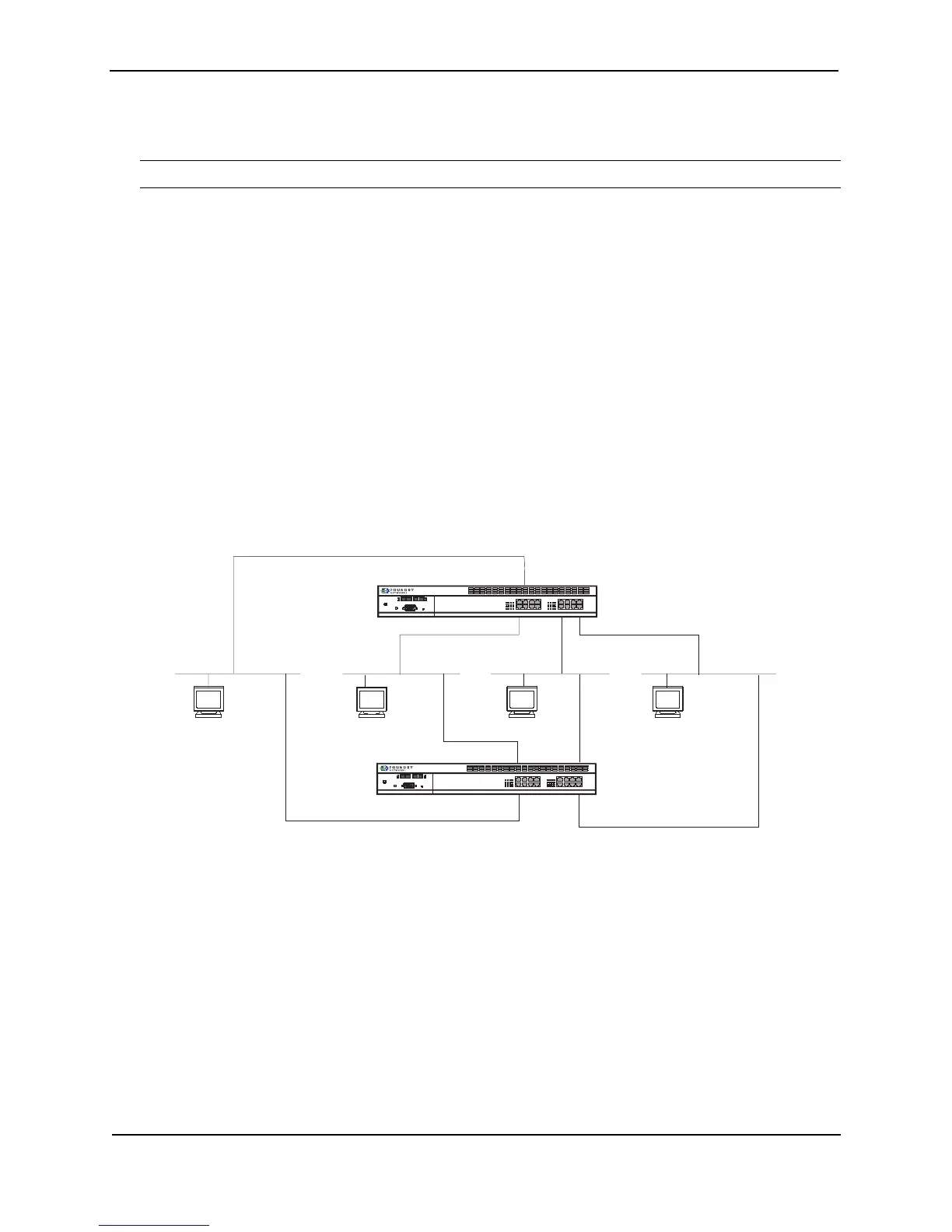
For example, in Figure 22.3, links on NetIron1 designated as e1 and e3 have failed and have transferred control to
their standby links on NetIron2; e4 and e2 remain as active links. This results in NetIron1, the router that was
originally assigned to serve as the active router, having a mix of active and standby links.
To bias all traffic and link traffic to the standby router, assign all other redundant links as track ports for all other
interfaces on the router. For example, on NetIron1, you would assign interfaces e1, e2, and e3 as track ports for
e4. Interfaces e1, e2, and e4 would thus track port e3. Interfaces e2, e3, and, e4 would track port e1. Interfaces
e1, e3, and e4 would track port e2. Configured in this manner, a failure on NetIron1 links e1 and e3 would make
NetIron2 the active router for all the links seen in Figure 22.4.
Because one router and all its links are active and the other router and its links are all in standby mode, all traffic
will be directed to the active router.
Figure 22.3 Failure of e1 and e3 links results in mixed active and standby links on NetIron1 without the use of
multiple track ports
Link
Acti vi ty
Lin k
Activity
Power
Con so l e
NetIron2
Link
Acti vi ty
Lin k
Activi ty
Power
Con so l e
NetIron1
PC 4 PC 3PC 2PC 1
e1 e2
e3
e4
SSSS
AAAA
A=Active
S=Standby
Active
Standby
XX
 Loading...