Foundry Switch and Router Installation and Configuration Guide
24 - 16 December 2000
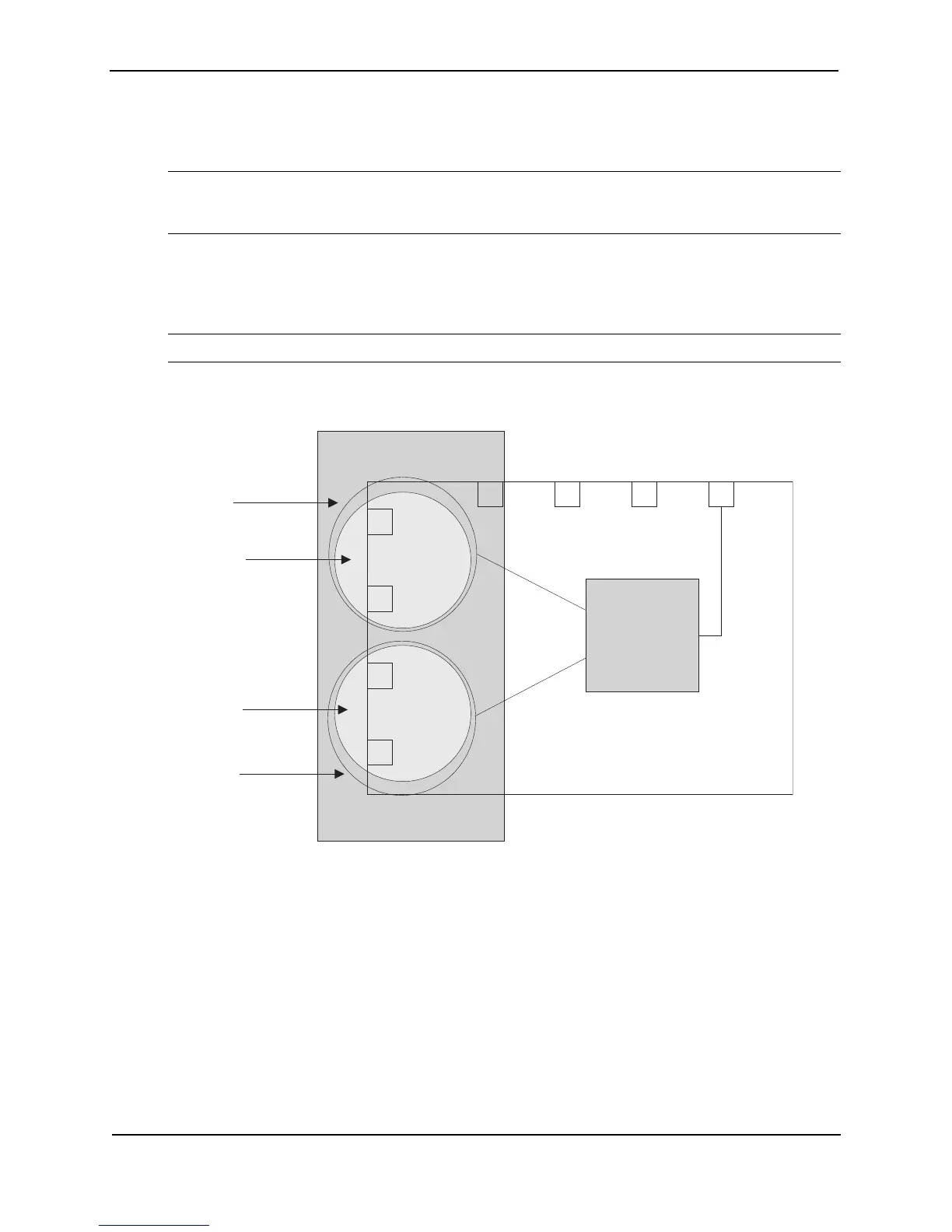
To create the configuration shown in Figure 24.4, perform the following tasks.
1. Create port-based VLANs 2 and 3.
NOTE: Protocol VLANs must always be within the boundaries of a port-based domain. Whenever port and
protocol VLANs operate on a system together, you must create the port-based VLAN before you create the
protocol VLAN. The protocol-based VLAN overlays the port-based VLAN.
2. Create AppleTalk protocol VLANs 2 and 3.
3. Configure router interfaces virtual 3 (v3) and virtual 5 (v5).
4. Configure physical interface port 8.
NOTE: Each of the above tasks is described in the following sections.
Figure 24.4 Routing between AppleTalk VLANs
USING THE CLI
BigIron(config)# vlan 2 by port
BigIron(config-vlan-2)# untag e3 to 4
BigIron(config-vlan-2)# atalk-proto
BigIron(config-vlan-atalk-proto)# static e3 to 4
BigIron(config-vlan-atalk-proto)# router-interface ve 5
BigIron(config-vlan-atalk-proto)# end
BigIron(config-vlan-2)# vlan 3 by port
BigIron(config-vlan-3)# untag e1 to 2
BigIron(config-vlan-3)# atalk-proto
BigIron(config-vlan-atalk-proto)# router-interface ve 3
5678
Router
Switch
AppleTalk
Protocol VLAN
400.50
Sales
Zone
100.50
Finance
Zone
Port-based
VLAN 2
AppleTalk
Protocol VLAN
Port-based
VLAN 3
200.50
Marketing
Zone
Virtual 3
Virtual 5
2
1
4
3
Network 100
Network 200
 Loading...