Configuring Virtual LANs (VLANs)
December 2000 25 - 29
Routing Between VLANs using Virtual Interfaces (routers only)
Foundry Layer 3 Switches offer the ability to create a virtual interface within a Layer 2 STP port-based VLAN or
within each Layer 3 protocol, IP sub-net, or IPX network VLAN. This combination of multiple Layer 2 and/or
Layer 3 broadcast domains and virtual interfaces are the basis for Foundry Networks’ very powerful Integrated
Switch Routing (ISR) technology. ISR is very flexible and can solve many networking problems. The following
example is meant to provide ideas by demonstrating some of the concepts of ISR.
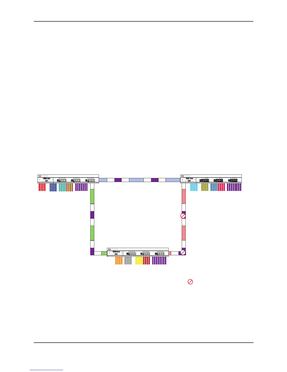
Example: Suppose you want to move routing out to each of three buildings in a network. Remember that the only
protocols present on VLAN 2 and VLAN 3 are IP and IPX. Therefore, you can eliminate tagged ports 25 and 26
from both VLAN 2 and VLAN 3 and create new tagged port-based VLANs to support separate IP sub-nets and
IPX networks for each backbone link.
You also need to create unique IP sub-nets and IPX networks within VLAN 2 and VLAN 3 at each building. This
will create a fully routed IP and IPX backbone for VLAN 2 and VLAN 3. However, VLAN 4 has no protocol
restrictions across the backbone. In fact there are requirements for NetBIOS and DecNet to be bridged among the
three building locations. The IP sub-net and IPX network that exists within VLAN 4 must remain a flat Layer 2
switched STP domain. You enable routing for IP and IPX on a virtual interface only on NetIron-A. This will provide
the flat IP and IPX segment with connectivity to the rest of the network. Within VLAN 4 IP and IPX will follow the
STP topology. All other IP sub-nets and IPX networks will be fully routed and have use of all paths at all times
during normal operation.
Figure 25.15 shows the configuration described above.
Figure 25.15 Routing between protocol-based VLANs
To configure the Layer 3 VLANs and virtual interfaces on the NetIron routers in Figure 25.15, use the following
procedure.
Vlan2 Vlan8 Vlan 3 Vlan 4
V5 IP/IPX V4 V5 IP/IPX V4V5 IP/IPX V4
V7 IP/IPX V4
V7 IP/IPX V4 V7 IP/IPX V4
V6 IP/IPX V4
V6 IP/IPX V4V6 IP/IPX V4
FastIron Workgroup
17
18
19
20
21
22
23
24
FDX
100
Link / Act
FDX
100
Link / Act
FDX
100
Link / Act
FDX
100
Link / Act
9
10
11
12
13
14
15
16
FDX
100
Link / Act
FDX
100
Link / Act
1
2
3
4
5
6
7
8
Power
Console
Link
Activity
Link
Activity
= STP Blocked VLAN
Building 3
NetIron-C
FastIron Workgroup
17
18
19
20
21
22
23
24
FDX
100
Link / Act
FDX
100
Link / Act
FDX
100
Link / Act
FDX
100
Link / Act
9
10
11
12
13
14
15
16
FDX
100
Link / Act
FDX
100
Link / Act
1
2
3
4
5
6
7
8
Power
Console
Link
Activity
Link
Activity
Building 1
NetIron-A
FastIron Workgroup
17
18
19
20
21
22
23
24
FDX
100
Link / Act
FDX
100
Link / Act
FDX
100
Link / Act
FDX
100
Link / Act
9
10
11
12
13
14
15
16
FDX
100
Link / Act
FDX
100
Link / Act
1
2
3
4
5
6
7
8
Power
Console
Link
Activity
Link
Activity
Building 2
NetIron-B
Vlan2 Vlan8 Vlan 3 Vlan 4
Vlan2 Vlan8 Vlan 3 Vlan 4
 Loading...
