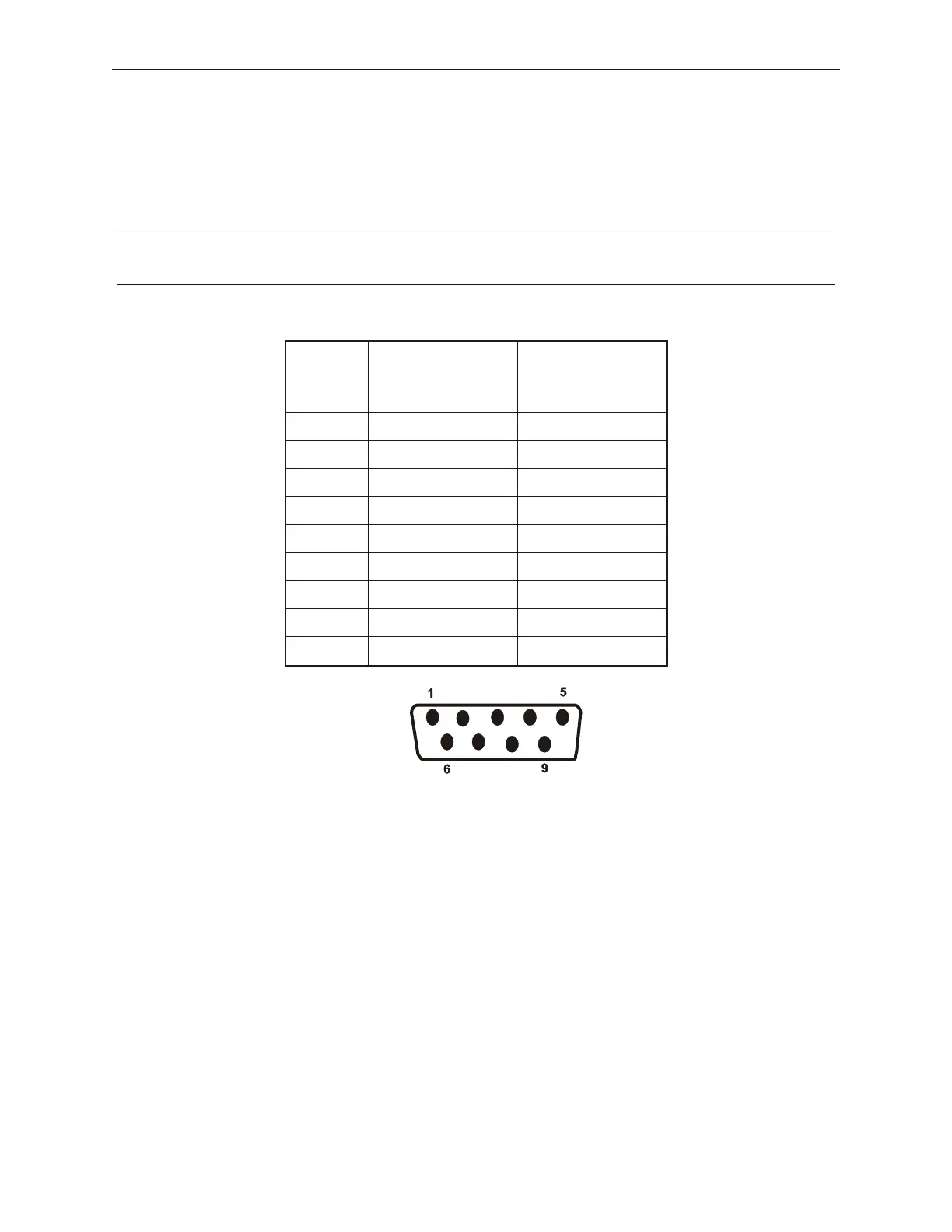
The following tables contain the connector signals for the ports on the TeamCOMBO
Board. A diagram of each connector and its pin out locations is shown after each table.
5.4.3 TeamCOMBO Board. Ports 1 and 2 Connector Signals
Connector type: Male D9
PIN # Signal When
DCT Power Mode
Signal when
Standard Com
Mode
1 NC CD
2 RX RX
3 TX TX
4 DTR DTR
5 SG SG
6 DSR DSR
7 RTS RTS
8 CTS CTS
9 +5V RI
5-20 Rev 3.0 90000291
TeamPoS 2000 MAINTENANCE MANUAL
Note: Pin outs may differ depending on jumper placement, see section 5.4.2.