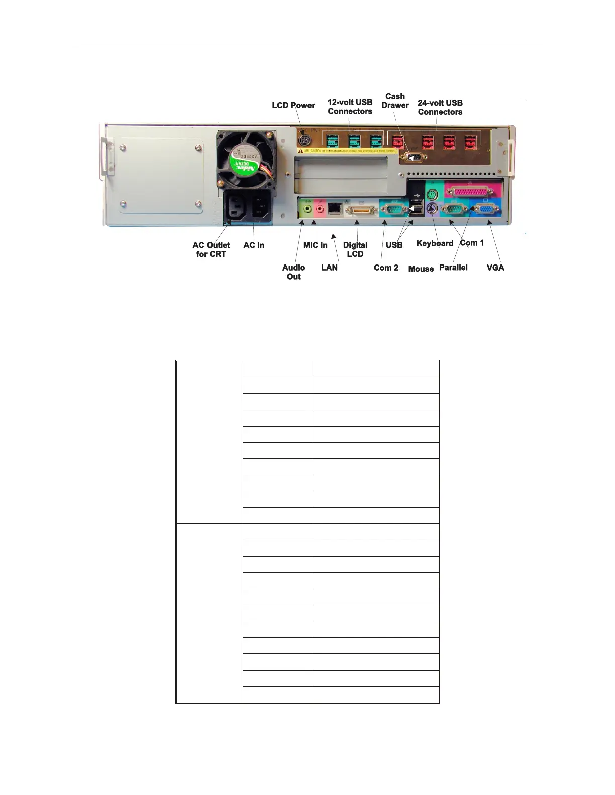
TeamPoS 2000 with TeamUSB Board Connector Layout with A Motherboard
When the TeamUSB board is installed, the top USB port becomes unavailable because it
is used as a hub for the new I-O board. A blanking label covers the port used.
5.12.3 TeamPoS 2000 with TeamUSB Board Connector Layout
with A Motherboard
Name Defnition
USB1 USB, 24VDC
USB2 USB, 24VDC
USB3 USB, 24VDC
PoS USB4 USB, 24VDC
Ports USB5 USB, 12VDC
USB6 USB, 12VDC
USB7 Not used on A motherboard
LCD PWR LCD Power
DRW Cash Drawer
KB Keyboard
M Mouse
COM1 Communications Port #1
COM2 Communications Port #2
PC Board LPT Parallel Interface
Ports VGA Analog Video
LCD Digital LCD Video
USB Universal Serial BUS (1)
MIC Microphone/Audio In
SPEAKER Speaker/Audio Out
LAN Local Area Network
90000291 Rev 3.0 5-79
TeamPoS 2000 MAINTENANCE MANUAL