GE Multilin 750/760 Feeder Management Relay 7-17
7 COMMUNICATIONS 7.4 MODBUS MEMORY MAP
7
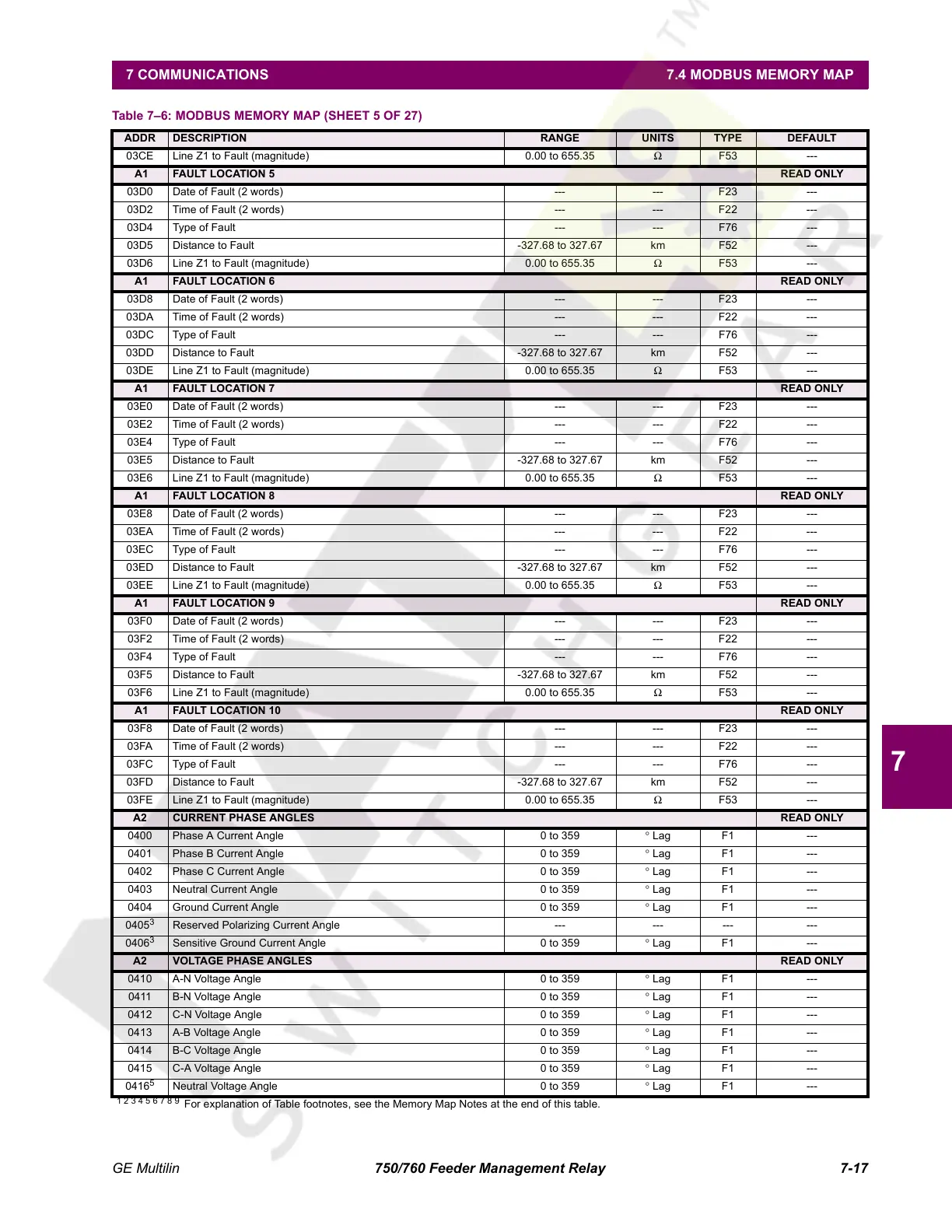
03CE Line Z1 to Fault (magnitude) 0.00 to 655.35 Ω F53 ---
A1 FAULT LOCATION 5 READ ONLY
03D0 Date of Fault (2 words) --- --- F23 ---
03D2 Time of Fault (2 words) --- --- F22 ---
03D4 Type of Fault --- --- F76 ---
03D5 Distance to Fault -327.68 to 327.67 km F52 ---
03D6 Line Z1 to Fault (magnitude) 0.00 to 655.35 Ω F53 ---
A1 FAULT LOCATION 6 READ ONLY
03D8 Date of Fault (2 words) --- --- F23 ---
03DA Time of Fault (2 words) --- --- F22 ---
03DC Type of Fault --- --- F76 ---
03DD Distance to Fault -327.68 to 327.67 km F52 ---
03DE Line Z1 to Fault (magnitude) 0.00 to 655.35 Ω F53 ---
A1 FAULT LOCATION 7 READ ONLY
03E0 Date of Fault (2 words) --- --- F23 ---
03E2 Time of Fault (2 words) --- --- F22 ---
03E4 Type of Fault --- --- F76 ---
03E5 Distance to Fault -327.68 to 327.67 km F52 ---
03E6 Line Z1 to Fault (magnitude) 0.00 to 655.35 Ω F53 ---
A1 FAULT LOCATION 8 READ ONLY
03E8 Date of Fault (2 words) --- --- F23 ---
03EA Time of Fault (2 words) --- --- F22 ---
03EC Type of Fault --- --- F76 ---
03ED Distance to Fault -327.68 to 327.67 km F52 ---
03EE Line Z1 to Fault (magnitude) 0.00 to 655.35 Ω F53 ---
A1 FAULT LOCATION 9 READ ONLY
03F0 Date of Fault (2 words) --- --- F23 ---
03F2 Time of Fault (2 words) --- --- F22 ---
03F4 Type of Fault --- --- F76 ---
03F5 Distance to Fault -327.68 to 327.67 km F52 ---
03F6 Line Z1 to Fault (magnitude) 0.00 to 655.35 Ω F53 ---
A1 FAULT LOCATION 10 READ ONLY
03F8 Date of Fault (2 words) --- --- F23 ---
03FA Time of Fault (2 words) --- --- F22 ---
03FC Type of Fault --- --- F76 ---
03FD Distance to Fault -327.68 to 327.67 km F52 ---
03FE Line Z1 to Fault (magnitude) 0.00 to 655.35 Ω F53 ---
A2 CURRENT PHASE ANGLES READ ONLY
0400 Phase A Current Angle 0 to 359 ° Lag F1 ---
0401 Phase B Current Angle 0 to 359 ° Lag F1 ---
0402 Phase C Current Angle 0 to 359 ° Lag F1 ---
0403 Neutral Current Angle 0 to 359 ° Lag F1 ---
0404 Ground Current Angle 0 to 359 ° Lag F1 ---
0405
3
Reserved Polarizing Current Angle --- --- --- ---
0406
3
Sensitive Ground Current Angle 0 to 359 ° Lag F1 ---
A2 VOLTAGE PHASE ANGLES READ ONLY
0410 A-N Voltage Angle 0 to 359 ° Lag F1 ---
0411 B-N Voltage Angle 0 to 359 ° Lag F1 ---
0412 C-N Voltage Angle 0 to 359 ° Lag F1 ---
0413 A-B Voltage Angle 0 to 359 ° Lag F1 ---
0414 B-C Voltage Angle 0 to 359 ° Lag F1 ---
0415 C-A Voltage Angle 0 to 359 ° Lag F1 ---
0416
5
Neutral Voltage Angle 0 to 359 ° Lag F1 ---
Table 7–6: MODBUS MEMORY MAP (SHEET 5 OF 27)
ADDR DESCRIPTION RANGE UNITS TYPE DEFAULT
1 2 3 4 5 6 7 8 9
For explanation of Table footnotes, see the Memory Map Notes at the end of this table.
Courtesy of NationalSwitchgear.com
 Loading...


