7-18 750/760 Feeder Management Relay GE Multilin
7.4 MODBUS MEMORY MAP 7 COMMUNICATIONS
7
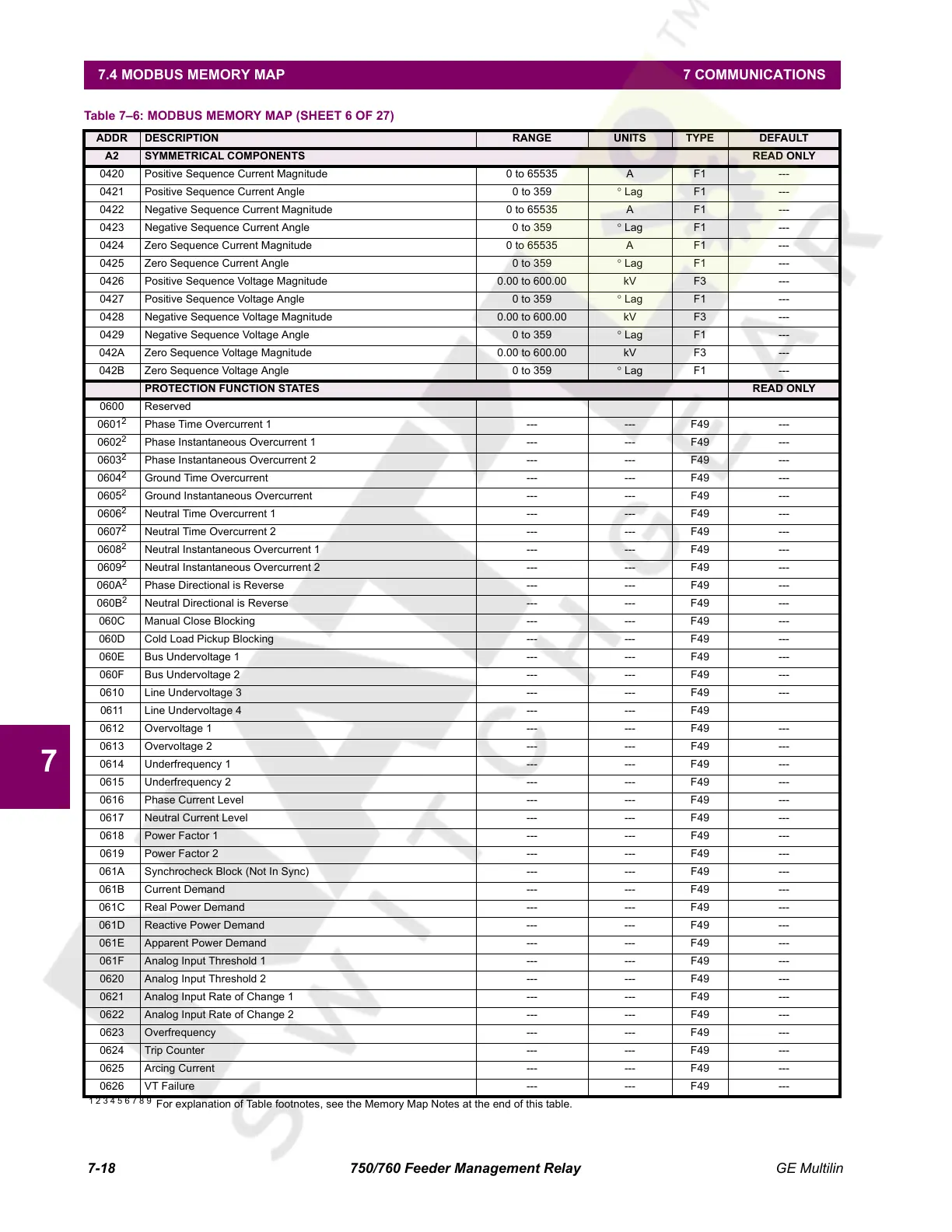
A2 SYMMETRICAL COMPONENTS READ ONLY
0420 Positive Sequence Current Magnitude 0 to 65535 A F1 ---
0421 Positive Sequence Current Angle 0 to 359 ° Lag F1 ---
0422 Negative Sequence Current Magnitude 0 to 65535 A F1 ---
0423 Negative Sequence Current Angle 0 to 359 ° Lag F1 ---
0424 Zero Sequence Current Magnitude 0 to 65535 A F1 ---
0425 Zero Sequence Current Angle 0 to 359 ° Lag F1 ---
0426 Positive Sequence Voltage Magnitude 0.00 to 600.00 kV F3 ---
0427 Positive Sequence Voltage Angle 0 to 359 ° Lag F1 ---
0428 Negative Sequence Voltage Magnitude 0.00 to 600.00 kV F3 ---
0429 Negative Sequence Voltage Angle 0 to 359 ° Lag F1 ---
042A Zero Sequence Voltage Magnitude 0.00 to 600.00 kV F3 ---
042B Zero Sequence Voltage Angle 0 to 359 ° Lag F1 ---
PROTECTION FUNCTION STATES READ ONLY
0600 Reserved
0601
2
Phase Time Overcurrent 1 --- --- F49 ---
0602
2
Phase Instantaneous Overcurrent 1 --- --- F49 ---
0603
2
Phase Instantaneous Overcurrent 2 --- --- F49 ---
0604
2
Ground Time Overcurrent --- --- F49 ---
0605
2
Ground Instantaneous Overcurrent --- --- F49 ---
0606
2
Neutral Time Overcurrent 1 --- --- F49 ---
0607
2
Neutral Time Overcurrent 2 --- --- F49 ---
0608
2
Neutral Instantaneous Overcurrent 1 --- --- F49 ---
0609
2
Neutral Instantaneous Overcurrent 2 --- --- F49 ---
060A
2
Phase Directional is Reverse --- --- F49 ---
060B
2
Neutral Directional is Reverse --- --- F49 ---
060C Manual Close Blocking --- --- F49 ---
060D Cold Load Pickup Blocking --- --- F49 ---
060E Bus Undervoltage 1 --- --- F49 ---
060F Bus Undervoltage 2 --- --- F49 ---
0610 Line Undervoltage 3 --- --- F49 ---
0611 Line Undervoltage 4 --- --- F49
0612 Overvoltage 1 --- --- F49 ---
0613 Overvoltage 2 --- --- F49 ---
0614 Underfrequency 1 --- --- F49 ---
0615 Underfrequency 2 --- --- F49 ---
0616 Phase Current Level --- --- F49 ---
0617 Neutral Current Level --- --- F49 ---
0618 Power Factor 1 --- --- F49 ---
0619 Power Factor 2 --- --- F49 ---
061A Synchrocheck Block (Not In Sync) --- --- F49 ---
061B Current Demand --- --- F49 ---
061C Real Power Demand --- --- F49 ---
061D Reactive Power Demand --- --- F49 ---
061E Apparent Power Demand --- --- F49 ---
061F Analog Input Threshold 1 --- --- F49 ---
0620 Analog Input Threshold 2 --- --- F49 ---
0621 Analog Input Rate of Change 1 --- --- F49 ---
0622 Analog Input Rate of Change 2 --- --- F49 ---
0623 Overfrequency --- --- F49 ---
0624 Trip Counter --- --- F49 ---
0625 Arcing Current --- --- F49 ---
0626 VT Failure --- --- F49 ---
Table 7–6: MODBUS MEMORY MAP (SHEET 6 OF 27)
ADDR DESCRIPTION RANGE UNITS TYPE DEFAULT
1 2 3 4 5 6 7 8 9
For explanation of Table footnotes, see the Memory Map Notes at the end of this table.
Courtesy of NationalSwitchgear.com
 Loading...


