GE Multilin 750/760 Feeder Management Relay 7-19
7 COMMUNICATIONS 7.4 MODBUS MEMORY MAP
7
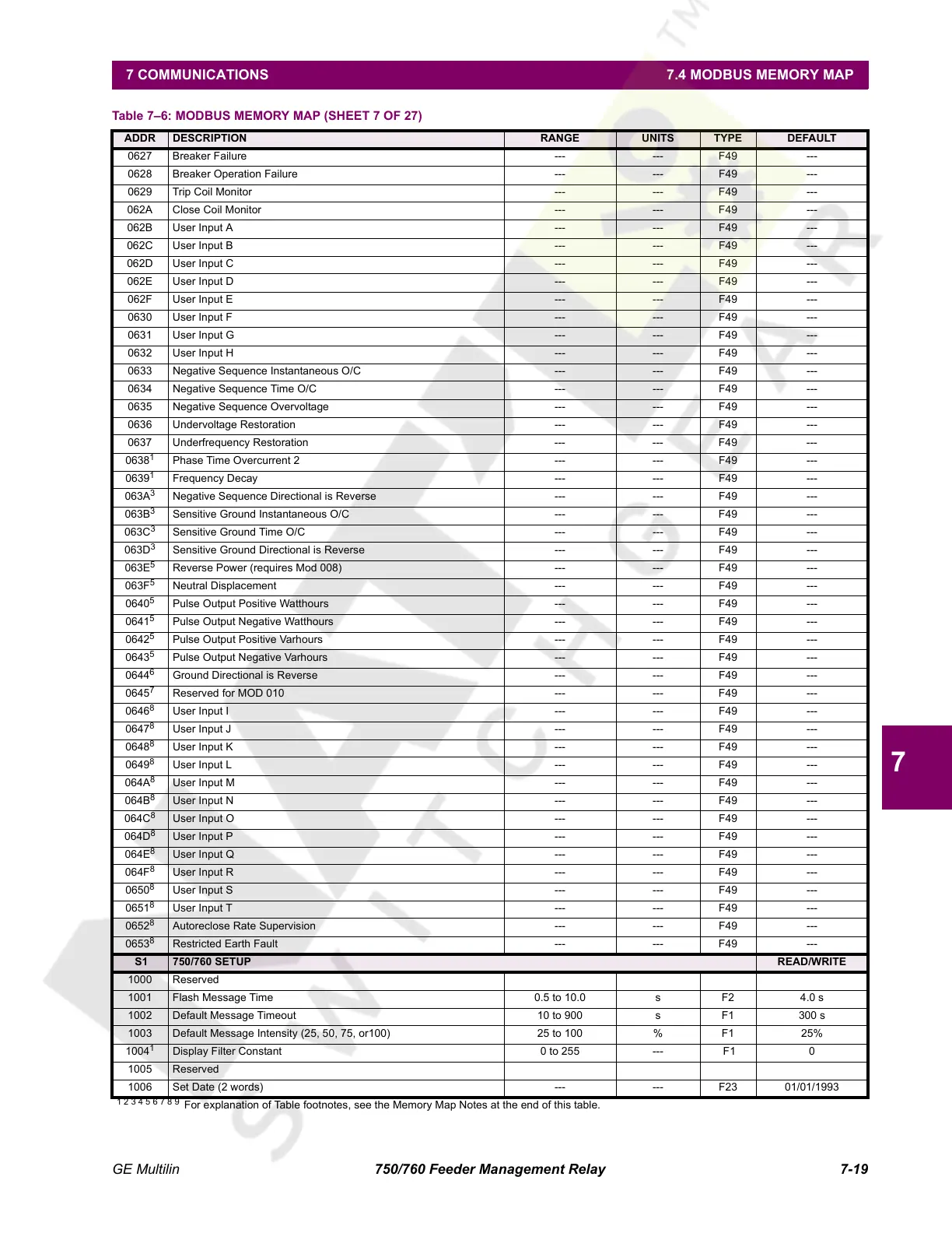
0627 Breaker Failure --- --- F49 ---
0628 Breaker Operation Failure --- --- F49 ---
0629 Trip Coil Monitor --- --- F49 ---
062A Close Coil Monitor --- --- F49 ---
062B User Input A --- --- F49 ---
062C User Input B --- --- F49 ---
062D User Input C --- --- F49 ---
062E User Input D --- --- F49 ---
062F User Input E --- --- F49 ---
0630 User Input F --- --- F49 ---
0631 User Input G --- --- F49 ---
0632 User Input H --- --- F49 ---
0633 Negative Sequence Instantaneous O/C --- --- F49 ---
0634 Negative Sequence Time O/C --- --- F49 ---
0635 Negative Sequence Overvoltage --- --- F49 ---
0636 Undervoltage Restoration --- --- F49 ---
0637 Underfrequency Restoration --- --- F49 ---
0638
1
Phase Time Overcurrent 2 --- --- F49 ---
0639
1
Frequency Decay --- --- F49 ---
063A
3
Negative Sequence Directional is Reverse --- --- F49 ---
063B
3
Sensitive Ground Instantaneous O/C --- --- F49 ---
063C
3
Sensitive Ground Time O/C --- --- F49 ---
063D
3
Sensitive Ground Directional is Reverse --- --- F49 ---
063E
5
Reverse Power (requires Mod 008) --- --- F49 ---
063F
5
Neutral Displacement --- --- F49 ---
0640
5
Pulse Output Positive Watthours --- --- F49 ---
0641
5
Pulse Output Negative Watthours --- --- F49 ---
0642
5
Pulse Output Positive Varhours --- --- F49 ---
0643
5
Pulse Output Negative Varhours --- --- F49 ---
0644
6
Ground Directional is Reverse --- --- F49 ---
0645
7
Reserved for MOD 010 --- --- F49 ---
0646
8
User Input I --- --- F49 ---
0647
8
User Input J --- --- F49 ---
0648
8
User Input K --- --- F49 ---
0649
8
User Input L --- --- F49 ---
064A
8
User Input M --- --- F49 ---
064B
8
User Input N --- --- F49 ---
064C
8
User Input O --- --- F49 ---
064D
8
User Input P --- --- F49 ---
064E
8
User Input Q --- --- F49 ---
064F
8
User Input R --- --- F49 ---
0650
8
User Input S --- --- F49 ---
0651
8
User Input T --- --- F49 ---
0652
8
Autoreclose Rate Supervision --- --- F49 ---
0653
8
Restricted Earth Fault --- --- F49 ---
S1 750/760 SETUP READ/WRITE
1000 Reserved
1001 Flash Message Time 0.5 to 10.0 s F2 4.0 s
1002 Default Message Timeout 10 to 900 s F1 300 s
1003 Default Message Intensity (25, 50, 75, or100) 25 to 100 % F1 25%
1004
1
Display Filter Constant 0 to 255 --- F1 0
1005 Reserved
1006 Set Date (2 words) --- --- F23 01/01/1993
Table 7–6: MODBUS MEMORY MAP (SHEET 7 OF 27)
ADDR DESCRIPTION RANGE UNITS TYPE DEFAULT
1 2 3 4 5 6 7 8 9
For explanation of Table footnotes, see the Memory Map Notes at the end of this table.
Courtesy of NationalSwitchgear.com
 Loading...


